


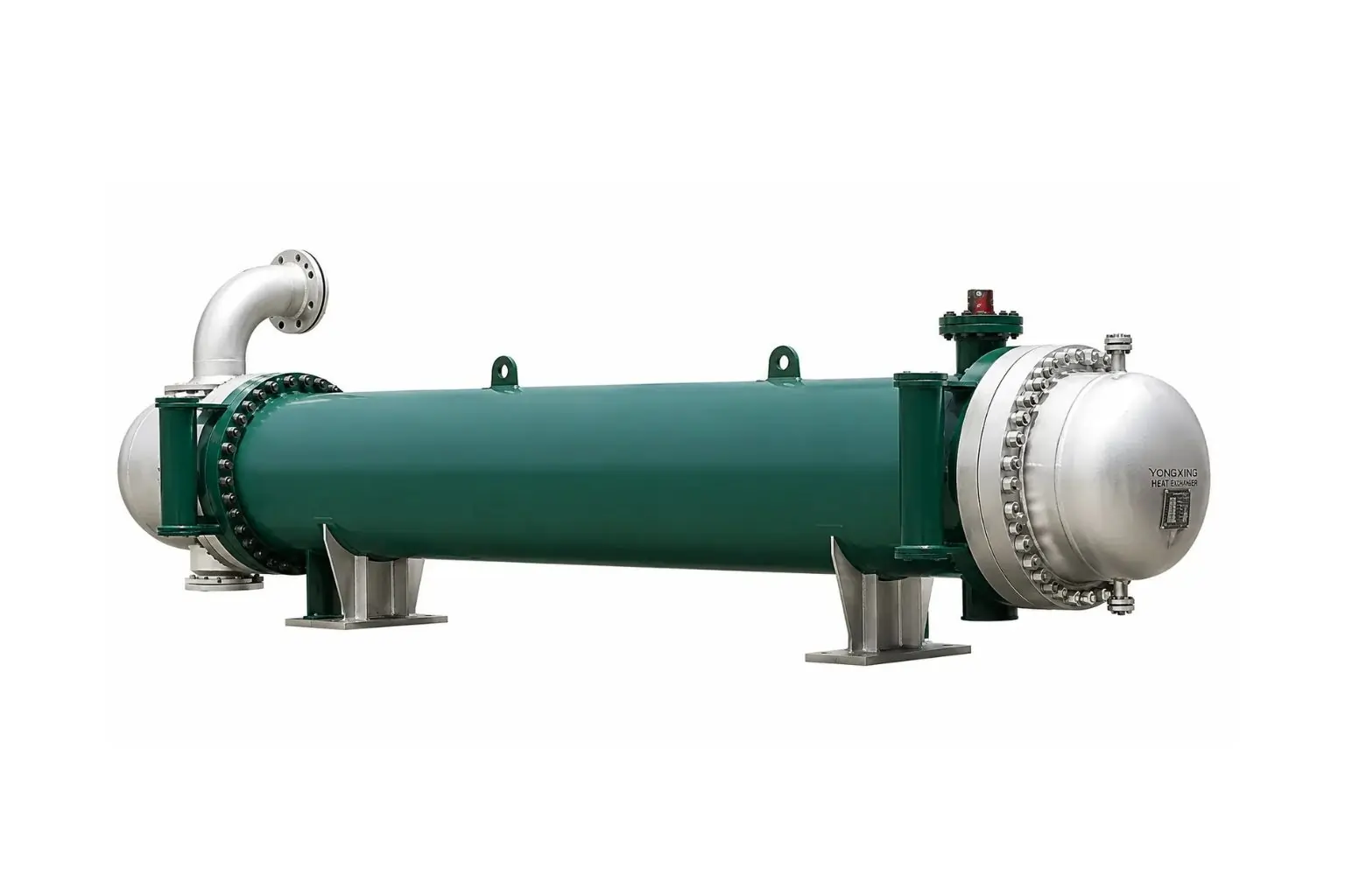
What Is a Floating Head Heat Exchanger?
A floating head heat exchanger is a specialized type of shell-and-tube heat exchanger designed to handle extreme temperature differences between the shell-side and tube-side fluids.Unlike fixed-tubesheet heat exchangers where both ends of the tube bundle are rigidly welded or bolted to the shell, a floating head design leaves one tube sheet fixed while the other is free to "float" (move axially) inside the shell. This mechanical freedom prevents the thermal stresses that typically cause tubes to buckle, bend, or shear away from the tube sheets during rapid temperature swings.
Key Components
- Shell and Shell Cover: The outer cylindrical vessel enclosing the entire assembly and containing the shell-side fluid.
- Tube Bundle: The assembly of parallel tubes through which one fluid flows.
- Fixed Tube Sheet: Anchored rigidly between the shell and the channel/bonnet at one end.
- Floating Tube Sheet: Attached to the opposite end of the tube bundle, unattached to the shell, allowing it to expand or contract freely.
- Floating Head Cover: A removable cover bolted to the floating tube sheet that directs the fluid flow into or out of the tubes without mixing with the shell-side fluid.
- Baffles: Internal plates that direct the shell-side fluid flow across the tubes to maximize heat transfer efficiency and support the tubes.
Why the Floating Head Design Exists
Early shell and tube exchangers used fixed tubesheets welded to both ends of the shell. These worked well when the temperature difference between the fluids was small and the fluids were clean. As process industries grew, particularly oil refining and chemical manufacturing, engineers faced two recurring problems:- Thermal stress: Large temperature differences between shell-side and tube-side fluids caused tubes and shells to expand by different amounts.
- Fouling and cleaning: Fluids such as crude oil, heavy hydrocarbons and untreated cooling water deposit scale, sludge and coke on heat transfer surfaces. A fixed tubesheet design makes the outside of the tubes nearly impossible to clean mechanically.
How a Floating Head Heat Exchanger Works
Understanding the flow path makes the design easier to follow.- Tube-side fluid enters the channel: The fluid that will flow inside the tubes enters through a nozzle on the channel at the front end. The channel distributes the fluid across the tube openings in the fixed tubesheet.
- Step Fluid flows through the tubes: The fluid travels along the length of the tubes toward the rear end of the exchanger.
- Shell-side fluid flows across the bundle: The second fluid enters through a nozzle on the shell and moves around the outside of the tubes. Baffles force it to cross the tube bundle repeatedly in a zigzag path rather than running straight along the tubes. This crossflow increases turbulence and improves heat transfer.
- Heat transfers through the tube wall: Thermal energy moves from the hotter fluid to the cooler one through the tube walls by conduction, and into and out of the fluids by convection.
- The floating head turns the tube-side flow: At the rear end, the tube-side fluid reaches the floating head. In a two-pass design, the floating head cover collects the fluid from one group of tubes and sends it back through the remaining tubes. In a single-pass design, the fluid simply exits.
- The bundle expands freely: As temperatures rise, the tubes lengthen. The floating tubesheet and head slide inside the shell to accommodate this change, so no axial stress builds up.
- Both fluids leave: The tube-side fluid exits through the channel outlet, and the shell-side fluid exits through the shell outlet nozzle.
Main Parts of a Floating Head Heat Exchanger
Each component serves a distinct purpose.- Shell: The cylindrical pressure vessel that surrounds the tube bundle and contains the shell-side fluid. It is typically made of rolled plate or pipe and carries nozzles for the shell-side inlet and outlet.
- Tube bundle: The assembly of tubes, baffles, tie rods, spacers and tubesheets. The tubes are the main heat transfer surface. Their diameter, wall thickness, length and material are selected to suit the duty.
- Fixed tubesheet (stationary tubesheet): A thick plate at the front end with holes drilled to receive the tubes. The tubes are expanded or welded into the holes to form a leak-tight joint. It is clamped between the channel flange and the shell flange.
- Floating tubesheet: The thick plate at the rear end that holds the other ends of the tubes. It is not attached to the shell, so it can move axially.
- Floating head cover: The cap bolted over the floating tubesheet. It contains the tube-side fluid at the rear end and, in multi-pass designs, redirects it back through the tubes.
- Channel (front head): The chamber at the front end that distributes the incoming tube-side fluid and collects the outgoing fluid. Pass partition plates inside the channel divide it for multi-pass arrangements.
- Baffles: Plates placed along the length of the bundle that guide shell-side flow across the tubes and support the tubes against sagging and vibration. Common types include single segmental, double segmental, disc-and-doughnut, and rod baffles.
- Tie rods and spacers: Rods fixed to the fixed tubesheet that hold the baffles at the correct spacing.
- Sealing strips: Thin strips attached along the bundle to block bypass flow in the gap between the bundle and the shell. Floating head exchangers need these because the bundle must be smaller than the shell to allow removal.
- Split ring or backing ring: In split-ring designs, a two-piece ring that secures the floating head to the floating tubesheet.
- Shell cover: The cover at the rear end of the shell that encloses the floating head. It is larger in diameter than the shell body in some designs to allow room for the head.
- Nozzles and flanges: Connections for the inlet and outlet of both fluids.
- Saddle supports:Fabricated supports that carry the weight of the exchanger. One saddle is usually fixed and the other has slotted holes so the exchanger can slide as the shell expands.
TEMA Nomenclature: How Floating Head Exchangers Are Classified
The Tubular Exchanger Manufacturers Association (TEMA) publishes the main standards for shell and tube exchangers. TEMA identifies each exchanger with a three-letter code that describes the front end head, the shell type and the rear end head. For example, an AES exchanger has:- A: removable channel with removable cover (front head)
- E: single-pass shell
- S: floating head with backing device (rear head)
TEMA also defines three mechanical standard classes:
- Class R: for severe duty in petroleum and related processing applications
- Class C: for moderate duty in commercial and general process applications.
- Class B: for chemical process service.
Types of Floating Head Heat Exchangers
Four TEMA rear-end head types fall under the floating head category: S, T, P and W.Type S: Floating Head With Backing Device (Split Ring)
The floating head is bolted to the floating tubesheet and held in position by a split backing ring, which sits behind the tubesheet. The shell cover is large enough to enclose the whole assembly.To remove the bundle, the shell cover is taken off, then the split ring and floating head cover. The bundle can then be pulled out of the shell.
Because the tubesheet sits close to the shell wall, the gap between bundle and shell is small. This allows a high tube count and efficient use of shell space. It is the most widely used floating head design and is common in refinery and petrochemical service. Typical example: AES.
Type T: Pull-Through Floating Head
The floating head is bolted directly to the floating tubesheet with no backing ring. When the shell cover is removed, the entire bundle, including the head, can be pulled out through the shell in one piece.This makes maintenance quick because no head disassembly is needed. The disadvantage is that the head is larger than the tube bundle, so the shell must be larger to let the head pass through. This creates a bigger gap between the bundle and the shell, which allows more bypass flow and lowers efficiency. The tube count for a given shell diameter is also lower. Sealing strips are used to limit bypass. Typical example: AET.
Type P: Outside Packed Floating Head
The floating tubesheet is extended through a packed joint at the rear end of the shell. The packing seals the shell-side fluid while allowing the head to slide.Because the packing can leak, this design is limited to low-pressure, non-hazardous services. Its advantage is that the shell-side fluid is sealed at the outside of the exchanger, which keeps the design simple. Typical example: AEP.
Type W: Externally Sealed Floating Tubesheet
The floating tubesheet is sealed at the shell end with a ring and packing or gasket arrangement. It is the least expensive of the floating designs.It is suitable only for low pressure and moderate temperature and for non-hazardous fluids, because there is a potential leak path at the seal. Typical example: AEW.
Choosing Between the Types
| Type | Bundle Removal | Tube Count | Pressure Capability | Typical Use |
|---|---|---|---|---|
| S (split ring) | Moderate effort | High | High | Refineries, petrochemicals |
| T (pull-through) | Easiest | Lower | High | Services needing frequent cleaning |
| P (outside packed) | Moderate | High | Low | Low-pressure, non-hazardous |
| W (externally sealed) | Moderate | High | Low | Economical, light duty |
Floating Head vs Fixed Tubesheet vs U-Tube Heat Exchanger
Shell and tube exchangers come in three main mechanical arrangements. Comparing them shows where the floating head design fits.Fixed tube sheet heat exchanger
Both tubesheets are welded to the shell. This is the simplest and cheapest design and provides the highest tube count for a given shell. However, the bundle cannot be removed, the shell side cannot be cleaned mechanically, and large temperature differences require an expansion joint in the shell. It suits clean fluids with small temperature differences.U-tube heat exchanger
The tubes are bent into a U shape and only one tubesheet is needed. Because the tubes can expand freely, thermal stress is not a problem, and the bundle is removable. The drawbacks are that the inside of the U-bends is hard to clean mechanically, individual tubes in the inner rows are difficult to replace, and the tube-side fluid must be fairly clean. It is often used for high-pressure service with clean tube-side fluids.Floating head heat exchanger
One tubesheet floats, which handles expansion, and the bundle is removable. Straight tubes are easy to clean and replace. The cost is higher and the construction more complex.| Feature | Floating Head | Fixed Tubesheet | U-Tube |
|---|---|---|---|
| Handles thermal expansion | Yes | Only with expansion joint | Yes |
| Removable bundle | Yes | No | Yes |
| Mechanical tube-side cleaning | Easy | Easy | Difficult |
| Mechanical shell-side cleaning | Easy | Not possible | Easy |
| Relative cost | High | Low | Medium |
| Tube count in given shell | Lower | Highest | Lower |
| Leak points | More | Fewer | Fewer |
| Best suited for | Fouling fluids, large temperature differences | Clean fluids, small temperature differences | Clean tube-side fluids, high pressure |
Advantages of Floating Head Heat Exchangers
- Absorbs thermal expansion: The free tubesheet lets the bundle expand and contract without stressing tubes, tubesheets or shell. This extends equipment life when temperatures change often or differ widely between fluids.
- Handles large temperature differences: It tolerates differences between the fluids that would damage a fixed tubesheet exchanger.
- Removable bundle: Inspection, repair and replacement are simpler because the whole bundle can be taken out of the shell.
- Cleanable on both sides: Tubes can be cleaned inside by brushing or hydro-jetting, and the bundle exterior can be cleaned once it is out of the shell. This makes the design well suited to fouling services.
- Easy tube replacement: Straight tubes can be plugged or replaced individually.
- Flexible design: It supports multiple tube passes, a range of baffle types and a wide choice of materials.
- Suitable for high pressure and temperature Types S and T are used in demanding refinery and chemical duties.
- Long service life: With proper maintenance, floating head exchangers can operate for decades.
Disadvantages and Limitations
- Higher cost: The floating tubesheet, head cover, backing ring, larger shell cover and more complex assembly increase material and fabrication cost.
- Lower tube density: The clearance needed between the bundle and the shell reduces the number of tubes that fit, so a larger shell is needed for the same surface area.
- Bypass flow: Fluid can pass through the gap between the bundle and the shell without contacting the tubes. Sealing strips and dummy tubes help but cannot eliminate it entirely.
- More leak paths: The floating head joint and shell cover joint add gasketed connections that can leak if not assembled correctly.
- Heavier and larger: The exchanger needs more floor space, plus a clear area at one end to pull the bundle out.
- Limited use of packed types: Types P and W are not recommended for toxic, flammable or high-pressure fluids because the packing can leak.
- Maintenance skill required: Reassembling the floating head correctly, including gasket seating and bolt tightening, takes experienced technicians.
Common Applications
Floating head heat exchangers appear wherever heavy-duty heat transfer and easy cleaning are priorities.- Oil refining: Crude oil preheat trains, overhead condensers, product coolers, reboilers and vacuum unit exchangers. Crude and residue streams foul heavily, so removable bundles are essential.
- Petrochemical and chemical plants: Process fluids with high temperatures or corrosive properties, reactor feed-effluent exchangers and condensers.
- Power generation: Lube oil coolers, feedwater heaters, steam condensers and auxiliary cooling systems.
- Oil and gas production: Gas processing, glycol regeneration, LNG facilities and offshore platforms, usually in corrosion-resistant materials.
- Fertilizer plants:Ammonia and urea processing, where high temperatures and pressures are common.
- Pulp and paper: Black liquor heaters and other fouling streams.
- Food, beverage and pharmaceutical processing: Stainless steel units where hygiene and cleanability matter.
- HVAC and industrial cooling: Large chillers and water-cooled systems where regular cleaning is needed.
Materials of Construction
Material selection depends on fluid chemistry, operating temperature, pressure, and cost.- Carbon steel: The standard choice for non-corrosive hydrocarbon and water services. It is strong, economical and easy to fabricate.
- Stainless steel (304, 316, 321): Used for corrosive fluids, food, beverage and pharmaceutical services, and for higher temperatures.
- Duplex and super duplex stainless steel: High strength and good resistance to chloride stress corrosion cracking, which makes them common in seawater and offshore service.
- Copper alloys (admiralty brass, cupronickel); Good thermal conductivity and resistance to water-side corrosion, often used for cooling water tubes.
- Titanium: Excellent resistance to seawater and chlorides, used where corrosion risk is high and long life is required.
- Nickel alloys (Inconel, Monel, Hastelloy): For severe corrosion or very high temperature conditions.
- Low-alloy steels (chrome-moly): For high-temperature refinery services such as hydrogen service or hot hydrocarbon streams.
Key Design Considerations
Designing a floating head exchanger involves both thermal and mechanical decisions.- Fluid allocation: The decision about which fluid goes on the shell side and which goes on the tube side affects performance and maintenance. Corrosive, fouling, high-pressure or toxic fluids usually go on the tube side, since tubes are easier to clean and replace than a shell.
- Heat duty and temperature profile: Engineers calculate the heat load and the log mean temperature difference (LMTD), then apply a correction factor for the flow arrangement.
- Tube passes: More passes raise tube-side velocity and heat transfer but also increase pressure drop. Two, four or six passes are common.
- Tube size and layout: Common outer diameters are 19 mm (3/4 inch) and 25 mm (1 inch). Tube layouts are triangular (more tubes, harder to clean) or square (easier to clean mechanically). Pitch affects both tube count and shell-side flow.
- Baffle design: Baffle type, cut and spacing control shell-side velocity, pressure drop and vibration risk. Closely spaced baffles raise heat transfer but also pressure drop.
- Fouling factors: Allowances are added to account for expected deposits during operation, which increases the required surface area.
- Pressure drop limits: Both sides have allowable pressure drops set by pump or compressor capability.
- Vibration analysis: Flow-induced vibration can damage tubes over time, so unsupported tube spans and flow velocities are checked.
- Thermal and mechanical stress: Tubesheet thickness, tube-to-tubesheet joint design, flange selection and shell thickness follow code calculations.
- Bundle removal clearance: Enough space must be left at the exchanger’s end to pull the bundle out. This is often overlooked during plant layout.
- Codes and standards: Typical references include ASME Boiler and Pressure Vessel Code Section VIII, TEMA standards and API 660 (shell and tube heat exchangers for general refinery services).
Maintenance Best Practices
Good maintenance prevents unplanned shutdowns and extends equipment life.- Routine inspection: Check for external leaks at flanges, nozzles and the floating head joint. Monitor temperature and pressure drop trends, because a rising pressure drop or falling heat transfer usually signals fouling. Cleaning methods
- Hydro-jetting: high-pressure water removes deposits from tubes and the bundle exterior.
- Mechanical cleaning: brushes or rotary tools clean the inside of tubes.
- Chemical cleaning: acids or solvents dissolve scale or hydrocarbon deposits.
- Steam or air blowing: removes loose deposits.
- Bundle pulling: At planned shutdowns, the bundle is removed for full inspection. Because the bundle is heavy, a crane or a dedicated bundle extractor is used.
- Non-destructive testing: Eddy current testing detects tube wall thinning, pitting and cracks. Ultrasonic testing checks shell and tubesheet thickness. Visual inspection covers the tubesheet faces and tube ends.
- Tube plugging and retubing: Failed tubes can be plugged to isolate them. When too many are plugged, the heat transfer area drops and the bundle needs retubing or replacement.
- Gasket and bolt care: Replace gaskets at every opening, clean flange faces, and tighten bolts in a cross pattern to the specified torque. Poor gasket seating is a leading cause of floating head leaks.
- Pressure testing: After reassembly, a hydrostatic test checks both the shell side and the tube side for leaks. For floating head units, a test ring or test flange is often used to test the shell side with the bundle in place.
- Corrosion control: Maintain water treatment programs, control flow velocities, and use sacrificial anodes or coatings where appropriate.
Common Problems and Troubleshooting
| Problem | Likely Cause | Typical Remedy |
|---|---|---|
| Reduced heat transfer | Fouling, scaling, air or gas pockets | Clean surfaces, vent trapped gas |
| High pressure drop | Blocked tubes, heavy fouling, excessive flow | Clean tubes, check flow rate |
| Leak at floating head | Worn gasket, uneven bolt load, damaged flange face | Replace gasket, re-torque, repair face |
| Fluid cross-contamination | Leaking tube or tube-to-tubesheet joint | Locate leak by pressure test, plug or retube |
| Tube failure | Corrosion, erosion, vibration, thermal fatigue | Identify cause, re-tube, change material or baffle layout |
| Poor thermal performance after cleaning | Bypass flow, damaged sealing strips | Restore sealing strips, check bundle fit |
| Vibration and noise | High shell-side velocity, long unsupported tube spans | Add support baffles, reduce flow |

