


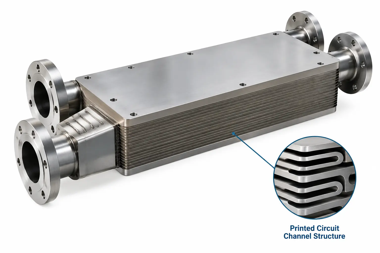
What is a printed circuit heat exchanger (PCHE)?
A printed circuit heat exchanger (PCHE) is a compact, high-efficiency heat exchanger built by chemically etching micro-channels into flat metal plates and joining them into a solid metal block via diffusion bonding.How PCHEs Are Built
- Photochemical Etching: Precision flow paths (typically 1–2 mm wide semicircles) are etched onto metal sheets like stainless steel, titanium, or nickel alloys.
- Diffusion Bonding: Stacked plates are joined under high temperature and pressure without any brazing, filler metal, or gaskets, forming a single, leak-free monolithic block.
- Modular Assembly: Individual bonded blocks are welded together and fitted with headers and nozzles to match required capacity.
Key Specifications & Advantages
- Size & Weight: Up to 75% to 85% smaller and lighter than traditional shell-and-tube heat exchangers.
- Pressure & Temperature Range: Withstands extreme pressures up to 1,250 bar (18,125 psi) and temperatures ranging from -253°C (deep cryogenic) up to 1,000°C.
- Thermal Effectiveness: Achieves high heat transfer effectiveness (up to 98%) with high surface area density.
- Durability: Resistant to vibrations, pressure pulsations, and thermal shock with no gaskets to fail.
Common Applications
- Hydrogen & LNG: Hydrogen refuelling stations, LNG regasification, and cryogenic gas processing.
- Power & Energy: Supercritical CO₂ (sCO₂) power cycles, concentrated solar power (CSP), and nuclear systems.
- Offshore & Marine: Marine fuel gas supply systems and offshore oil and gas processing.
Typical characteristics (approximate, vary by manufacturer and design):
- Channel size: about 1 to 2 mm wide
- Surface area density: often above 1,000 m² per m³
- Size and weight: commonly 4 to 6 times smaller and lighter than a shell and tube exchanger of equal duty
- Pressure: several hundred bar in standard designs
- Temperature: from cryogenic levels up to roughly 800 °C or more, depending on the alloy
- Thermal effectiveness: above 95% is achievable in counterflow
How does a printed circuit heat exchanger work?
A PCHE works by passing a hot fluid and a cold fluid through alternating layers of etched plates. Heat conducts through the thin metal wall that separates each pair of channels, moving from the hot stream to the cold stream without the fluids ever mixing.Two features make this efficient. First, the channels are tiny, so a large amount of heat transfer area fits inside a small block. Second, the walls between channels are thin, so the heat has only a short path to travel. The basic heat duty relationship is:
Q=UATlm
Here Q is the heat duty, U is the overall heat transfer coefficient, A is the heat transfer area and ΔT_lm is the log mean temperature difference. A PCHE raises both U and A for a given volume, which is why the block can be so small.
Flow arrangements
- Counterflow: the fluids move in opposite directions. This gives the highest effectiveness and allows a very close temperature approach.
- Crossflow: the fluids move at right angles. It simplifies header layout but gives lower effectiveness.
- Cross-counterflow: a mix of both, often used to fit nozzle and header positions without losing much performance.
- Parallel (co-current) flow: rarely used, because it limits how close the outlet temperatures can get.
- Multi-stream: three or more fluids can exchange heat in one core, replacing several separate exchangers.
How a PCHE is made: photochemical etching and diffusion bonding
The manufacturing process is what gives a printed circuit heat exchanger its strength and compactness. It follows five main steps:- Plate preparation: flat metal plates, typically a few millimetres thick, are cut and cleaned.
- Photochemical etching: a photoresist pattern is applied and acid removes the exposed metal, leaving semicircular channels roughly 1 to 2 mm wide. The pattern is the "printed circuit".
- Stacking: etched plates for the hot and cold streams are stacked in alternating order, with a blank cover plate on top.
- Diffusion bonding: the stack is heated under high pressure, below the metal's melting point. Atoms migrate across the plate interfaces and fuse them into a single solid block with parent-metal strength.
- Header and nozzle welding: headers and nozzles are welded to the finished core, then the unit is pressure tested and inspected.
Common materials
- Stainless steel 316L and 304L: the most common choice, with good corrosion resistance and wide availability.
- Duplex stainless steel (such as 2205): higher strength and better resistance to chloride stress corrosion, common offshore.
- Titanium: excellent resistance to seawater and aggressive chemicals.
- Nickel alloys (such as Alloy 617, 625 and 800H): used for very high temperature or highly corrosive duties, including advanced power cycles.
Types of PCHE channel geometry
The shape of the etched channel sets the balance between heat transfer and pressure drop. Designers choose among four main patterns:| Channel Type | Heat Transfer | Pressure Drop | Best Suited To |
|---|---|---|---|
| Straight | Lowest | Lowest | Clean, low-pressure-drop duties and simple designs |
| Zigzag (Wavy) | High | Highest | The most common choice; compact duties where pressure drop is acceptable |
| S-shaped Fin | High | Lower than zigzag | Duties needing strong performance with reduced pumping power |
| Airfoil Fin | High | Very low in published studies | Pressure-drop-critical duties; newer and less widely deployed |
Advantages of printed circuit heat exchangers
- Compact and lightweight: the high surface area density cuts footprint and weight sharply, which lowers structural and installation costs on platforms and ships.
- Very high pressure capability: the diffusion-bonded block handles pressures that gasketed or brazed designs cannot.
- Wide temperature range: suitable from cryogenic LNG service to high-temperature power cycles, depending on the alloy.
- High thermal effectiveness: counterflow layouts allow very close temperature approaches, which improves energy recovery.
- Leak-resistant core: with no gaskets or brazed joints between plates, the risk of cross-leakage is very low.
- Corrosion resistance by material choice: stainless, duplex, titanium and nickel alloys are all available.
- Multi-stream capability: several fluids can be handled in one unit, reducing piping and equipment count.
- Long service life: the monolithic core resists fatigue and vibration damage well when operated within design limits.
Limitations and challenges
- Fouling sensitivity: the narrow channels clog easily, so fluids must be clean or well filtered.
- Hard to clean mechanically: the channels cannot be opened or brushed; cleaning relies on chemical or hydraulic methods.
- Higher pressure drop: small channels create more flow resistance than larger passages, which raises pumping or compression power.
- Higher unit cost: etching, bonding and alloy costs make a PCHE more expensive per unit of area, although total installed cost is often lower in space-critical or high-pressure projects.
- Limited repair options: a damaged core usually cannot be repaired in the field.
- Thermal stress limits: rapid start-up, shutdown or temperature swings can cause fatigue, so ramp rates must be controlled.
- Limited supplier base: only a small number of manufacturers produce them, so lead times can be long.
Applications of printed circuit heat exchangers
PCHEs are used wherever high pressure, extreme temperatures, limited space or low weight make other exchangers impractical.| Industry | Typical PCHE Use |
|---|---|
| LNG and Gas Processing | LNG vaporization, gas cooling, liquefaction and regasification, including floating units. |
| Offshore Oil and Gas | Gas compression cooling, gas heating and processing on platforms and FPSOs where space and weight are limited. |
| Hydrogen | Pre-cooling at high-pressure hydrogen refuelling stations and hydrogen processing. |
| Nuclear and Advanced Reactors | Heat transfer loops in high-temperature gas-cooled and other next-generation reactor designs. |
| Supercritical CO₂ Power Cycles | Recuperators and coolers in supercritical CO₂ (sCO₂) Brayton cycles for power generation and waste heat recovery. |
| Concentrated Solar Power | Heat exchange between the solar loop and the power cycle. |
| Chemical and Petrochemical | High-pressure reactor feed and effluent heat exchange, and synthesis gas cooling. |
PCHE vs shell and tube vs plate heat exchanger
A PCHE wins on pressure, temperature and compactness, while shell and tube and plate-and-frame designs win on cost and ease of cleaning. The table shows typical differences.| Feature | Printed Circuit (PCHE) | Shell and Tube | Gasketed Plate-and-Frame |
|---|---|---|---|
| Pressure Capability | Very high (hundreds of bar) | High, design dependent | Low to moderate, limited by gaskets |
| Temperature Capability | Cryogenic to roughly 800 °C or more | Very wide | Limited by gasket material |
| Size and Weight | Smallest and lightest at high pressure | Largest | Compact |
| Fouling Tolerance | Low; needs clean fluids | Moderate to high | Low to moderate |
| Cleaning | Chemical or hydraulic only | Mechanical and chemical | Open and clean by hand |
| Leak Risk | Very low (no plate gaskets) | Tube-to-tubesheet joints | Gasket leaks possible |
| Unit Cost | Highest | Moderate | Lowest |
| Best For | High-pressure, space-critical, clean duties | General industrial duties with fouling | Low-pressure, frequently cleaned duties |
How to select a printed circuit heat exchanger
Choose a PCHE when pressure, temperature or space is the limiting factor and the fluids are clean. Check these points before specifying one:- Operating pressure and temperature: confirm design and test conditions, including upset cases.
- Fluid cleanliness: clean, filtered fluids are essential. If heavy fouling is expected, consider another type.
- Material compatibility: match the alloy to corrosion, chloride, hydrogen or high-temperature conditions.
- Thermal duty and temperature approach: a close approach favours a counterflow PCHE.
- Allowable pressure drop: pick the channel geometry that fits the pressure drop budget.
- Space and weight limits: offshore, marine and skid-mounted projects benefit most.
- Codes and certification: confirm the pressure vessel code, such as ASME Section VIII or the Pressure Equipment Directive, plus any inspection requirements.
- Lifecycle cost: compare total installed and operating cost, not only purchase price.
- Supplier experience: ask for references in similar fluids and operating conditions.
Maintenance, cleaning and inspection
Good maintenance of a PCHE is mostly prevention, because the channels cannot be opened up.- Filter the fluids: install fine strainers or filters upstream, sized to the manufacturer's guidance.
- Control temperature and pressure ramps: follow the specified start-up and shutdown rates to avoid thermal fatigue.
- Monitor performance: track pressure drop and temperature approach over time. A rising pressure drop or a widening approach points to fouling.
- Clean chemically or hydraulically: use cleaning agents and flushing procedures approved for the core material and the fouling type.
- Avoid contamination and dead-heading: keep debris out during construction and commissioning, and avoid trapped liquids that can freeze or corrode.
- Inspect and test: run periodic leak and pressure tests, and keep records of operating conditions against the design envelope.
Frequently asked questions about PCHEs
What does PCHE stand for?
PCHE stands for printed circuit heat exchanger. It is also known as a diffusion bonded heat exchanger.Why is it called a "printed circuit" heat exchanger?
The flow channels are made by photochemical etching, the same family of processes used to make printed circuit boards, and the etched pattern looks similar.How is a PCHE different from a plate heat exchanger?
A gasketed plate heat exchanger uses pressed plates sealed with gaskets, which limits pressure and temperature. A PCHE bonds etched plates into a solid block with no gaskets, so it handles far higher pressure and temperature.What are the main advantages of a PCHE?
The main advantages are compact size, low weight, very high pressure and temperature capability, high thermal effectiveness and a leak-resistant core.Can a PCHE handle dirty or fouling fluids?
Not well. The channels are very small, so fluids need to be clean or well filtered. For heavy fouling, shell and tube or plate-and-frame designs are usually a better fit.Where are printed circuit heat exchangers used?
They are used in LNG plants, offshore oil and gas platforms, hydrogen refuelling, nuclear and advanced reactors, supercritical CO2 power cycles, concentrated solar power and chemical processing.Can a PCHE be repaired?
Repair is very limited because the core is a solid bonded block. Damaged channels may sometimes be plugged, but replacement is more common, so prevention through filtration and controlled operation matters.Conclusion
A printed circuit heat exchanger is the right choice when a duty combines high pressure, high or cryogenic temperature, tight space and clean fluids. Its etched, diffusion-bonded core delivers high thermal effectiveness in a fraction of the size of conventional exchangers, which is why PCHEs are now standard in LNG, offshore, hydrogen and advanced power applications.If your fluids are heavily fouling or your pressure is low, a shell and tube or plate-and-frame exchanger may be more economical. For a project-specific recommendation, share your fluids, pressures, temperatures and duty with a qualified PCHE manufacturer.

