


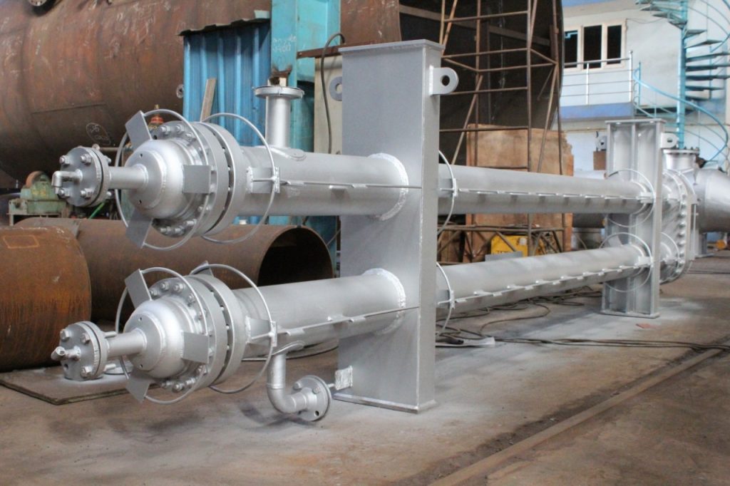
Hairpin Heat Exchanger: Design, Applications & Industry Insights
A hairpin heat exchanger (often called a double-pipe exchanger) is an industrial device featuring one or more U-shaped tubes inside a larger outer shell. It is highly prized for its true counter-current flow design, which maximizes heat transfer and effortlessly handles extreme temperatures, high pressures, and temperature-cross conditions.A hairpin heat exchanger is a primary example of a double-pipe or concentric pipe heat exchanger. It is also widely classified as a specialized type of shell-and-tube heat exchanger.
Key Design Features
- U-Tube Bundle: The core of the unit consists of tubes bent 180 degrees into a hairpin shape, which allows the bundle to expand and contract freely without thermal stress or the need for expansion joints.
- True Counter-current Flow: Unlike traditional multi-pass shell and tube exchangers, hairpin designs allow the shell-side and tube-side fluids to flow in opposite directions across the entire length of the exchanger, optimizing the Logarithmic Mean Temperature Difference (LMTD).
- Temperature Crossing: They are highly efficient for "temperature cross" scenarios where the hot fluid outlet becomes cooler than the cold fluid outlet.
Common Types
- Double-Pipe: Features a single inner tube housed within an outer pipe, commonly used for high-fouling or highly viscous fluids.
- Multi-Tube: Contains multiple tubes inside a single shell, offering a larger surface area while maintaining the compact, efficient hairpin profile.
Drawbacks
While hairpin heat exchangers are highly efficient for specific thermal duties, their main disadvantages include high initial costs, limited scalability for very large applications, and an increased risk of leaks due to multiple inter-unit connectionsHairpin Heat Exchanger – Product Information
| Type | Description | Best Suited For |
|---|---|---|
| Double Pipe | Single inner tube inside an outer shell (bare or finned). Simplest hairpin design. | Small duties, high pressure, slurries, abrasive fluids, and low flow rates. |
| Multi-Tube | Multiple smaller tubes (3–50) bundled inside a larger hairpin shell (up to 30" diameter). | Medium to large duties, chemical processing, oil & gas applications, and fouling services. |
| Finned Tube | Longitudinal fins on inner tubes provide greater heat transfer area in a compact design. | Low-velocity fluids, viscous streams, and installations with limited space. |
| Rod-Through / Straight Tube | Removable straight-tube bundle with rod-through cleaning capability. | Severe fouling services, easy maintenance requirements, and thermal expansion environments. |
Is a hairpin heat exchanger better than a shell and tube?
Whether a hairpin heat exchanger is "better" depends entirely on your specific process needs. Hairpin exchangers are often superior for applications requiring high thermal efficiency, frequent temperature crosses, or handling severe thermal expansion. However, standard shell and tube designs handle larger flow rates and heavy industrial scales more cost-effectively.When Hairpin is Better:
- Temperature Crosses: Hairpins use pure counter-current flow, meaning hot and cold fluids move in opposite directions, maximizing temperature differences. This is ideal if your hot fluid outlet needs to be cooler than the cold fluid outlet.
- Thermal Expansion: The U-tube "hairpin" design allows the bundle to float, easily absorbing thermal stress from extreme temperature differentials without needing expansion joints.
- Maintenance & Fouling: The modular, removable-bundle design makes hairpin exchangers easier to disassemble and clean. They are excellent for fluids prone to fouling (e.g., slurries or abrasive materials).
- Smaller Duties: If your required surface area is small (less than \(300\) sq. ft.) or duty is under \(500\) kW, hairpins are usually the more economical choice.
When Shell and Tube is Better:
- High Flow Rates: Traditional shell and tube models are optimized for massive flow volumes.
- Large Industrial Scale: For major processes requiring immense surface areas (e.g., thousands of square feet), a single shell and tube unit is typically much cheaper and takes up less physical space than the multiple hairpin sections required to do the same job.
Technical Specifications
| Parameter | Double Pipe | Multi-Tube |
|---|---|---|
| Shell OD Range | 2" – 6" | Up to 30" |
| Pressure Rating | Full vacuum to ~14,600 psi | Full vacuum to ~14,000 psi |
| Temperature Range | −300°F to 1,400°F (cryogenic to high-temperature); ΔT capability greater than 300°F / 149°C | |
| Heat Transfer Surface Area | 1 – ~100 ft² | 1 – 10,000+ ft² (finned); 1 – 6,000 ft² |
| Flow Configuration | True counter-current flow (no correction factor required) | |
| Design Standards | ASME Code Certified; TEMA Standards | |
| Tube Materials | Carbon Steel, Stainless Steel (e.g., SA 312 TP 304), Admiralty Brass, and various specialty alloys | |
How a Hairpin Heat Exchanger Works
The operating principle is straightforward: two concentric pipes (one inside the other) are bent into a U-shape, creating a double-pipe hairpin arrangement. One fluid travels through the inner pipe; the other travels through the annular space between the inner and outer pipes.The key thermal advantage comes from counterflow operation ,the two fluids travel in opposite directions, maximizing the temperature gradient across the entire length of the exchanger. This means the hairpin design consistently achieves higher Logarithmic Mean Temperature Differences (LMTD) compared to parallel-flow equipment.
Core Design Elements
- Double-pipe or multi-tube construction inside a shell
- U-bend return head at one end; fixed connections at the other
- Counterflow configuration for maximum thermal efficiency
- Modular sections (legs) that can be added or removed to adjust capacity
- Finned inner tubes available to increase surface area when treating viscous fluids
Counterflow vs. Parallel Flow: Why It Matters
In a counterflow arrangement, the hot fluid enters where the cold fluid exits, and vice versa. This maintains a more uniform temperature driving force along the entire heat transfer length, resulting in:- Closer temperature approaches (within 2–5°C in optimized designs)
- Up to 20–30% greater thermal efficiency versus equivalent parallel-flow units
- Lower required heat transfer area for the same thermal duty
Hairpin heat exchanger components
- Inner Tubes: The primary heat transfer surface. In multi-tube designs, this is a bundle of smaller tubes; in double-pipe designs, it is a single central pipe.
- Outer Shell (Barrel): The larger outer pipe that contains the inner tubes and holds the shell-side fluid.
- U-Bend (Hairpin): The curved section connecting the straight legs of the tubes. It allows for a single-pass or multi-pass flow and handles thermal expansion.
- Tubesheet: A circular plate that secures the tubes and separates the shell-side fluid from the tube-side fluid.
- Baffles: Internal plates inside the shell that direct fluid flow across the tubes, creating turbulence to maximize heat transfer efficiency.
- Tie Rods & Spacers: Structural rods that hold the baffle assembly firmly in place within the tube bundle.
- Fins: Attached to the outside of the inner tubes in some configurations to increase the surface area for heat transfer.
Comparison with Other Heat Exchangers
| Parameter | Hairpin | Shell & Tube | Plate (PHE) | Double Pipe | Spiral |
|---|---|---|---|---|---|
| Flow Type | True Counter-Current | Multi-Pass (Mixed) | Counter / Parallel | True Counter-Current | Counter-Current |
| Heat Transfer Efficiency | High | Medium | Very High | Low–Medium | High |
| Pressure Rating | Up to 14,600 psi | Up to ~6,000 psi | Up to ~300 psi | Up to 14,600 psi | Up to ~1,500 psi |
| Temperature Cross | Excellent | Poor | Good | Good | Moderate |
| Footprint / Size | Compact | Large | Very Compact | Compact | Medium |
| Thermal Expansion | Handles Freely (U-Bend) | Needs Expansion Joint | Flexible Plates | Handles Freely | Self-Compensating |
| Fouling / Cleaning | Moderate | Easy (Removable Bundle) | Easy (Disassemble) | Moderate | Self-Cleaning |
| Surface Area | 1–6,000 ft² | Up to 100,000+ ft² | Up to ~50,000 ft² | Small (<500 ft²) | Up to ~15,000 ft² |
| Best For | High Pressure/Temperature, Temperature Cross, Cyclic Duty | Large-Scale Processes | Low-Pressure Liquid Duties | High-Pressure, Small Duty | Fouling or Viscous Fluids |
| Cost | Medium | Medium–High | Low–Medium | Low | Medium |
| Code / Standard | ASME / TEMA | ASME / TEMA | ASME / AHRI | ASME / TEMA | ASME |
Hairpin Heat Exchanger Applications Across Industries
The versatility of hairpin heat exchanger applications is one of its strongest selling points. Below are the primary industries and use cases where this technology delivers proven results.1. Oil & Gas and Refining
Refineries rely heavily on industrial hairpin heat exchangers for crude preheating, hydrocarbon cooling, and inter-stage heat recovery in distillation columns. The ability to handle fouling fluids , heavy crude, slurries, and waxy hydrocarbons without shutting down the entire unit (thanks to the removable bundle design) makes the hairpin design operationally advantageous.2. Chemical and Petrochemical Processing
Highly corrosive or reactive chemical streams demand heat exchangers built from exotic alloys such as Hastelloy, Inconel, or duplex stainless steel. Hairpin units accommodate these materials with relative ease, and their modular nature allows capacity to scale as production expands.3. Power Generation
Steam condensers, feedwater heaters, and lube oil coolers in power plants benefit from the compact footprint and high-pressure capability of the hairpin design. A high pressure hairpin heat exchanger can operate at pressures exceeding 200 bar when properly engineered, making it suitable for supercritical steam applications.4. Food, Beverage & Pharmaceutical
Sanitary-grade hairpin exchangers with polished stainless-steel surfaces and crevice-free welds meet FDA and 3-A standards. Their ease of cleaning in place (CIP) is critical for hygienic processing of dairy, beverage, and biopharmaceutical products.5. HVAC and Industrial Cooling
For large commercial HVAC systems and process cooling loops, hairpin units provide efficient chilled water or glycol cooling without the large real-estate footprint of shell-and-tube units. Their low pressure-drop profile reduces pump energy costs.Advantages and Limitations: An Honest Assessment
No heat exchanger technology is universally superior. Below is a balanced evaluation to help engineers and buyers make informed decisions.| ✔ Advantages | ✘ Limitations |
|---|---|
| True counterflow = highest thermal efficiency | Higher cost per unit area vs. large shell-and-tube |
| Compact, modular design, easy to expand | Shell-side cleaning can be more challenging |
| Handles high pressures and temperatures | Not ideal for very large heat duties (>50 MW) |
| Easy mechanical cleaning of tube-side | Longer footprint for multi-section units |
| Suitable for viscous, fouling, or abrasive fluids | Requires careful support structure design |
| Lower capital cost for smaller duties | Limited tube-side flow configurations |
| Flexible materials of construction |
Key Engineering Insights and Expert Recommendations
Sizing and Thermal Design
Proper sizing is the single most critical factor in getting the best performance from a hairpin type heat exchanger. Engineers should follow these steps:- Define the thermal duty: establish inlet/outlet temperatures, flow rates, and allowable pressure drop for both streams.
- Select the number of legs (sections): each U-bend section adds heat transfer area; most designs run 2–8 legs.
- Specify tube diameter and wall thickness based on pressure rating and fluid velocity requirements (typical tube-side velocity: 1–3 m/s for liquids).
- Choose enhanced surface geometry: longitudinally finned tubes increase effective surface area by 2–4× for viscous oil or gas services.
- Verify thermal performance using LMTD correction factors for any deviation from pure counterflow (e.g., multi-pass configurations).
Materials Selection for High-Pressure and Corrosive Service
When specifying a high pressure hairpin heat exchanger, material selection is non-negotiable. Consider:- Carbon steel (ASTM A106/A333): standard duty, temperatures up to 425°C
- 316L stainless steel: mild corrosion, pharmaceutical, food-grade service
- Duplex stainless (2205, 2507): chloride environments, offshore applications
- Hastelloy C-276 / Inconel 625: severe acid or high-temperature gas service
- Titanium: seawater cooling, highly oxidizing media
Maintenance Best Practices
One of the hairpin design's most underappreciated advantages is maintenance accessibility. Follow these best practices to maximize equipment life:- Schedule tube-side mechanical cleaning every 12–18 months in fouling-prone services
- Inspect U-bend welds annually using dye-penetrant or radiographic testing in high-cycle services
- Monitor differential pressure across each section as an early indicator of fouling
- For shell-side fouling, chemical cleaning in-situ is typically more effective than mechanical rodding
- Replace gaskets at every disassembly , never reuse compressed-fiber or spiral-wound gaskets
Real-World Example: Refinery Feedstock Preheating
A mid-size petroleum refinery in Southeast Asia replaced four aging shell-and-tube exchangers with a train of six-leg industrial hairpin heat exchangers for crude oil preheating duty at 180°C and 75 bar operating pressure.Results after 18 months of operation:
- Thermal duty maintained at 4.2 MW with an outlet temperature approach of 8°C
- Fouling resistance values remained within design specification , enabled by higher tube-side fluid velocity in the narrower annular space
- Mechanical cleaning turnaround time reduced from 5 days (shell-and-tube) to under 18 hours per unit
- Total footprint reduced by 35% compared to the previous shell-and-tube bank
How to Select a Reliable Hairpin Heat Exchanger Manufacturer
The quality of your equipment is only as good as the manufacturer behind it. When evaluating a hairpin heat exchanger manufacturer, verify the following:Certifications and Standards
- ASME Section VIII, Division 1 or 2 (pressure vessel code) , mandatory for most industrial applications
- PED (Pressure Equipment Directive) compliance for European projects
- API 660 or TEMA standards for oil and gas service
- ISO 9001:2015 quality management certification
- Third-party shop inspection capability (DNV, Bureau Veritas, Lloyd's Register)
Engineering and Design Capability
A credible manufacturer should offer in-house thermal rating using software such as HTRI Xchanger Suite or ASPEN Exchanger Design and Rating (EDR), not just manual calculations. Ask for documented design reports with LMTD calculations, tube velocity data, and fouling factor assumptions.Fabrication Quality Indicators
- Full radiographic or ultrasonic examination of welds on high-pressure units
- Hydrostatic pressure testing at 1.3–1.5× design pressure
- Material traceability documentation (mill test reports)
- Dimensional and visual inspection records
Hairpin vs. Shell-and-Tube vs. Plate Heat Exchanger: Quick Comparison
| Parameter | Hairpin | Shell & Tube | Plate |
|---|---|---|---|
| Pressure Rating | Up to 700 bar+ | Up to 700 bar+ | Typically <25 bar |
| Temperature Range | Up to 600°C+ | Up to 600°C+ | Up to ~250°C |
| Thermal Efficiency | Very High (counterflow) | Medium–High | Very High |
| Footprint | Compact (modular) | Moderate–Large | Very Compact |
| Fouling Tolerance | High | High | Low–Medium |
| Maintenance Access | Easy tube-side | Moderate | Easy (gasketed) |
| Capital Cost (small duty) | Low–Medium | Medium–High | Low |
Conclusion
The hairpin type heat exchanger remains a top-performing solution for demanding thermal processing applications.Its counterflow design, mechanical robustness, ease of maintenance, and modular scalability make it the preferred choice for engineers working in oil and gas, chemicals, power, and specialty manufacturing. When properly sized, fabricated to code, and sourced from a qualified hairpin heat exchanger manufacturer, this technology consistently delivers reliable, long-service performance with a predictable cost of ownership.
Whether you need a compact unit for a laboratory pilot plant or a multi-million-dollar bank of high pressure hairpin heat exchangers for a refinery expansion, the fundamental engineering principles remain the same: maximize heat transfer surface, maintain counterflow, select appropriate materials, and insist on certified fabrication quality.
Take the time to define your thermal duty precisely, engage a knowledgeable manufacturer early in the design process, and plan for systematic maintenance , and the hairpin design will serve your operation dependably for 20+ years.

