


What Is a Shell and Tube Heat Exchanger?
A Shell and tube heat exchanger is a device that transfers heat between two fluids. It uses a large cylindrical shell containing a bundle of parallel tubes. One fluid flows inside the tubes, and the other fluid flows around them inside the shell to swap heat safely without mixing.It is the most common type of heat exchanger used in heavy industries due to its robust design, high-pressure tolerance, and versatile configuration options.
Core Working Principle
The device operates on a simple conduction and convection process. One fluid flows through a bundle of internal tubes (called the tube-side fluid), while a second fluid flows around the outside of those tubes inside a large cylindrical casing (called the shell-side fluid). Heat passes directly through the tube walls from the hotter fluid to the cooler one.Key Components
- Shell: The large, high-pressure outer cylinder that contains the tube bundle and the shell-side fluid.
- Tubes: A series of small-diameter pipes that carry the tube-side fluid. They can be straight or bent into a U-shape
- Tube Sheets: Thick plates that secure both ends of the tubes in place, keeping the shell-side and tube-side fluids structurally separated.
- Baffles: Internal plates positioned inside the shell. They support the long tubes to prevent vibrations and force the shell fluid to travel in a zigzag pattern, increasing contact time and efficiency.
- Channels/Heads: End compartments that receive the tube-side fluid, directing it into and out of the tube bundle.
Common Classifications
Shell and tube heat exchangers are categorized by how their internal tube bundles are engineered:| Type | Design Features | Best Used For |
|---|---|---|
| Fixed Tube Sheet | Tubes are welded directly to the shell; no relative movement is allowed. | Clean fluids with low temperature differences. |
| U-Tube | Tubes are bent into a continuous "U" shape and anchored at only one tube sheet. | High temperature fluctuations, allowing for thermal expansion. |
| Floating Head | One tube sheet is fixed while the other floats freely inside the shell. | Dirty fluids, as the tube bundle can be completely removed for cleaning. |
Advantages
- High-Pressure and Temperature Capability: The robust cylindrical geometry inherently handles demanding industrial operating environments.
- Scalability: Provides a large surface area for heat exchange within a relatively compact footprint.
- Ease of Maintenance: Designs like floating-head or removable channel covers allow the tube bundle to be easily inspected, cleaned, or replaced.
- Material Versatility: Can be manufactured from a wide assortment of exotic metals and alloys to resist aggressive, highly corrosive process fluids.
How Does a Shell and Tube Heat Exchanger Work?
The heat exchange process relies entirely on two fundamental principles of thermodynamics:Convection: Thermal energy transfers from the hotter fluid to the tube wall, and from the tube wall to the cooler fluid.
Conduction: Heat travels directly through the solid metal of the tube walls from the high-temperature side to the low-temperature side.
Key Components
The Shell: The outer Pressure Vessels or housing that holds the shell-side fluid. It features an inlet and an outlet to circulate the fluid around the tube bundle.The Tubes: A bundle of parallel metal tubes through which the tube-side fluid travels.
Baffles: Internal metal sheets placed in an alternating up and down or side to side pattern. They force the shell-side fluid to travel perpendicular across the tube bundle multiple times, which prevents stagnation, creates turbulence, and maximizes heat transfer.
Tube Sheets: Plates situated at the ends of the shell that hold the tubes securely in place and act as a seal to prevent the shell-side and tube-side fluids from mixing.
How the Flow Works
Tube-Side Fluid: Enters through the header (or channel) at one end of the exchanger, flows straight through the inside of the tubes, and exits on the opposite end (or loops back to exit on the same end).Shell-Side Fluid: Enters the shell, snakes its way around the outside of the hot/cold tubes guided by the baffles, and exits from an outlet on the opposite side of the shell.
Because the two fluids have a temperature difference, thermal energy naturally moves from the warmer medium to the cooler medium. This allows the exchanger to either cool down hot processes or heat up cold processes depending on the application.
Shell and Tube Heat Exchanger Design Details
The design of a shell and tube heat exchanger balances thermal hydraulics (achieving the required heat transfer) with mechanical integrity (withstanding operational pressures, temperatures, and structural stress). Industrial design is strictly governed by engineering standards like the ASME Boiler and Pressure Vessel Code (Section VIII) for mechanical strength and TEMA (Tubular Exchanger Manufacturers Association) for structural and thermal layout guidelines.Thermal and Hydraulic Core Design Factors
An optimized thermal design ensures efficient heat transfer while managing the allowable pressure drop across both the tube and shell sides.Log Mean Temperature Difference (LMTD):
- Dictates the effective driving force for heat transfer between the hot and cold fluids.
- Corrected using a geometric factor (F) to account for non-pure countercurrent flow in multi-pass configurations.
Fluid Allocation:
- Tube Side: Typically reserved for fluids prone to fouling, corrosive streams, high-pressure fluids, or the hotter stream (tubes are easier to clean, insulate, or replace with exotic alloys).
- Shell Side: Reserved for viscous fluids, condensing vapor, or boiling streams to utilize complex flow paths and optimize pressure drop.
Velocity Management:
- Higher fluid velocity increases the heat transfer coefficient but exponentially raises the pressure drop.
- Low velocity must be avoided on both sides to prevent fluid stagnation, fouling, and sedimentation.
Critical Mechanical Components and Geometry
The internal geometry of an exchanger modifies fluid velocity and turbulence to maximize heat exchange efficiency.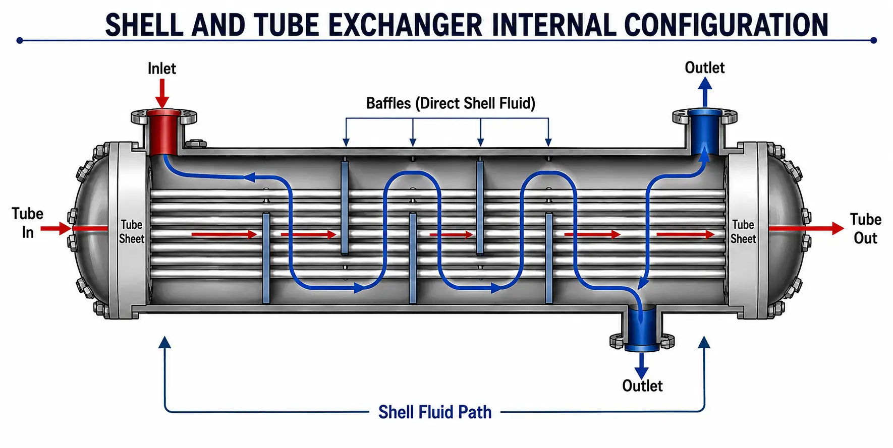
Tube Bundle Geometry:
- Tube Pitch: The center-to-center distance between adjacent tubes. TEMA mandates a minimum pitch of 1.25 × Tube Outer Diameter Do.
- Tube Layout Angle: Tubes are arranged in Triangular layouts (30° or 60°) for high structural density and maximum heat transfer, or Square layouts (45° or 90°) to leave open mechanical cleaning lanes between tubes.
Baffle Configuration:
- Baffle Cut: The segment of a circular baffle plate cut away to allow fluid to pass. It typically ranges from 15% to 45% of the shell diameter.
- Baffle Spacing: The distance between baffle plates. It is designed between 20% to 100% of the internal shell diameter to induce turbulence without causing excessive pressure drop or fluid dead zones.
Types of Shell and Tube Heat Exchangers
Shell and tube heat exchangers are mainly divided into three primary geometric types: fixed tubesheet, U-tube, and floating head designs. These devices use a bundle of parallel tubes inside a cylindrical shell to transfer heat between two fluids without letting them mix.Main Design Types
- Fixed Tubesheet: The tubesheet is welded directly to the shell at both ends. It is low-cost and easy to clean inside the tubes, but cannot handle high thermal expansion between the shell and tubes unless an expansion joint is added.
- U-Tube: The tubes are bent in a U-shape. This design lets the tube bundle expand and contract freely with temperature changes, though cleaning the inside of the U-bends is difficult.
- Floating Head: One tubesheet is fixed while the other can move ("float") inside the shell. This allows full thermal expansion and makes it very easy to pull out the entire tube bundle for cleaning.
TEMA Classifications by Service
- Class R: Built for heavy-duty refinery and petroleum applications with strict safety rules.
- Class C: Made for general commercial and industrial process applications.
- Class B: Designed for chemical process service.
Applications of shell and tube heat exchangers
- Oil, Gas, and Petrochemical: Heavily utilized in petroleum refining and SAGD facilities. They function as process heaters, hydrocarbon coolers, gas condensers, and reboilers that must safely operate under extreme pressures and temperatures.
- Power Generation: Critical in closed-loop systems to maximize thermal efficiency. They are predominantly used in condensers to turn steam back into water after spinning turbines, and as boiler feedwater heaters and turbine oil coolers.
- HVAC and Refrigeration: Used in large commercial buildings to chill water or act as condensers and evaporators in heat pumps, transferring heat between refrigerants and water based on seasonal needs.
- Food and Beverage: Employed for gentle and precise temperature control, such as milk pasteurization in dairies and rapidly cooling fermented beverages prior to bottling.
- Pharmaceuticals and Chemicals: Required for strict process heating, solvent recovery, and temperature regulation in reactor vessels.
- Marine and Offshore: Utilized for seawater cooling, desalination systems, and ballast water treatment. In these environments, tubes are built with corrosion-resistant materials like cupronickel.
Core Functions
- Depending on the production process, these exchangers can operate as:
- Condensers: Converting hot vapors into liquids.
- Evaporators: Boiling liquids into vapors using a hot fluid on the opposite side.
- Process Coolers: Reducing the temperature of hot industrial fluids.
- Process Heaters: Raising the temperature of a fluid
Advantages of Shell and Tube Heat Exchangers
Shell and tube heat exchangers are highly durable, cost-effective devices designed to transfer thermal energy between two fluids. Their robust, leak-proof construction allows them to safely handle extreme temperatures and pressures, making them the industry standard for demanding environments like oil refining, chemical processing, and power generation.Key advantages include:
- Extreme Operating Limits: Capable of withstanding very high pressures (often exceeding 30 bar) and extreme temperatures (from sub-zero up to hundreds of degrees Celsius).
- Leak Prevention & Safety: Their welded construction and reduced reliance on internal gaskets (unlike plate designs) drastically minimize the risk of leaks. They are the safest choice for handling toxic or hazardous fluids.
- Cost-Effectiveness: Relatively inexpensive to manufacture and maintain over their operational lifetime. They generally require fewer replacements of wear items like gaskets.
- Easy Maintenance: Removable tube bundles allow for straightforward cleaning, individual tube replacement, and mechanical inspection.
- Fluid Versatility: Can easily accommodate a wide range of fluid types, including gases, steam, highly viscous oils, and liquids with suspended solids.
- Customizable Heat Transfer: Surface area can be readily adjusted by altering tube length, diameter, and the number of passes to optimize efficiency.
Materials Used in Shell and Tube Heat Exchangers
The selection of materials for shell and tube heat exchangers depends on fluid chemistry, operating temperatures, pressures, and corrosion risks. Because the tubes experience different chemical exposures and fluid velocities than the shell, a single exchanger often utilizes a combination of different metals or alloys.Tube Materials
Tubes require materials with high thermal conductivity and excellent resistance to erosion corrosion caused by high-velocity fluids.Carbon Steel:
- Properties: High strength, excellent heat transfer, low cost.
- Applications: Non-corrosive fluids, oils, hydrocarbons, and high-pressure steam.
Stainless Steel(304 / 316):
- Properties: Excellent corrosion resistance, good thermal properties.
- Applications: Chemical processing, food and beverage, and mildly corrosive water.
Copper Alloys (Brass, Cupronickel):
- Properties: High thermal conductivity, excellent biofouling resistance.
- Applications: Sea water cooling, marine environments, and steam condensers.
Duplex Stainless Steel:
- Properties: Twice the strength of austenitic stainless steels; high resistance to chloride stress corrosion cracking.
- Applications: Desalination plants, chemical reactors, and high-chloride environments.
Super Alloys (Titanium, Hastelloy, Inconel):
- Properties: Extreme corrosion resistance, stable at ultra-high temperatures.
- Applications: Acid handling, offshore oil platforms, and highly aggressive chemical processing.
Shell and Component Materials
The shell, channels, and tube sheets do not require high thermal conductivity, so materials are chosen primarily for structural integrity, weldability, and cost-effectiveness.- Carbon Steel: The industry standard for shells due to its strength, ease of welding, and low cost.
- Low-Alloy Steel (Chrome-Moly): Used for high-temperature and high-pressure applications (e.g., refineries) to resist creep and hydrogen attack.
- Clad Materials: To save costs in highly corrosive applications, a thick carbon steel plate is metallurgically bonded (clad) with a thin layer of titanium or stainless steel on the side facing the corrosive fluid.
Why Choose United Cooling Systems Pvt. Ltd.?
- Over 20 Years of Experience
- Certified Manufacturing (ISO 9001:2015)
- Advanced Testing and Fabrication Facility
- Custom-Built Heat Transfer Solutions
- Worldwide Delivery & After-Sales Support
Maintenance Tips and Best Practices
To ensure optimal performance:- Periodically inspect for fouling or clogging
- Use appropriate cleaning methods (chemical or hydro jetting)
- Monitor for pressure changes
- Replace gaskets and seals on time
- Schedule yearly maintenance checks
Other Products by United Cooling Systems Pvt. Ltd.
- Air-Cooled Heat Exchangers (ACHEs): An efficient, fan-driven system that cools fluids using ambient air—ideal for locations where water is scarce or expensive.
- Fin Tube Heat Exchanger:Compact and high-performance, these are designed with extended surface area (fins) to boost thermal transfer in compact spaces.
- Double Pipe Heat Exchanger:Suitable for smaller capacity applications, especially where precise temperature control is needed.
- Pressure Vessels:Designed for safe storage of gases or liquids under pressure, built to ASME or IS codes with high durability.
📞 Request a Quote or Technical Support
Looking for high-efficiency Shell and Tube Heat Exchangers? Let us help you find the right solution tailored to your operational demands. 👉 Contact Us TodayConclusion
If you’re looking for a durable, efficient, and custom-designed shell and tube heat exchanger, United Cooling Systems Pvt. Ltd. is your trusted partner. With years of experience and a strong focus on quality, we provide thermal solutions that work reliably across all industries.FAQs – Shell and Tube Heat Exchangers
1. What is the definition of a shell and tube heat exchanger?A shell and tube heat exchanger is a mechanical device used to transfer heat between two fluids without allowing them to mix. It consists of a large outer shell that holds a bundle of tubes. One fluid flows inside the tubes, while the other fluid flows around the tubes within the shell. Effective heat transmission through the tube walls is guaranteed by this configuration.
2. What is the working principle of a shell and tube heat exchanger?
The exchanger works on the principle of indirect heat exchange, where heat is transferred through the walls of the tubes from the hot fluid to the cold one. The mechanism relies on conduction through the tube material and convection within the fluids, making it both reliable and efficient.
3. What is the general principle behind heat exchangers?
All heat exchangers work on the fundamental concept of thermal energy transfer between two fluids. This transfer can occur either through direct contact or via a separating wall, as in shell and tube designs. The main aim is to achieve heating or cooling of a process stream efficiently.
4. What does "approach" mean in a shell and tube heat exchanger?
In heat exchanger terminology, "approach" refers to the temperature difference between the cold fluid outlet and the hot fluid outlet. A smaller approach value means better efficiency, but it may require a larger heat transfer area. It is an important factor during the design stage.
5. What is the difference between shell side and tube side?
- Tube side: The fluid flows inside the tubes. It is generally suitable for clean fluids and higher pressure applications.
- Shell side: The fluid circulates outside the tubes, inside the shell. This side is better for fluids with higher viscosity or a tendency to foul.
6. Why is viscous fluid usually routed through the shell side?
Viscous fluids are routed through the shell side because the shell offers more flow area and better flexibility in design. Baffles can be used to increase turbulence, which improves heat transfer and reduces the chance of clogging or pressure drop—especially important when handling thick fluids like oils or syrups.
7. What are the major types of shell and tube heat exchangers?
- Fixed Tube Sheet: Simple in construction and economical; suitable when frequent cleaning is not required.
- U-Tube Design: Allows for thermal expansion; ideal when space is limited.
- Floating Head Type: Provides easy access for cleaning both shell and tube sides; ideal for processes with fouling or high contamination.
Industry prefers shell and tube heat exchangers because they are:
- Durable and long-lasting
- Suitable for high-pressure and high-temperature operations
- Customizable based on application
- Scalable and easy to install
- Relatively easy to maintain with proper design
9. How are shell and tube heat exchangers maintained?
To ensure smooth operation and long life, the following maintenance practices are recommended:
- Regular cleaning of the tubes (chemical or mechanical)
- Checking for pressure drops and unusual temperature readings
- Inspecting for scaling or fouling inside the tubes or shell
- Replacing worn-out gaskets, seals, or damaged tubes
- Periodic testing for leaks and corrosion
10. What is the typical life span of a shell and tube heat exchanger?
With proper material selection, correct design, and regular maintenance, shell and tube heat exchangers can serve reliably for 15 to 25 years or even more. Lifespan also depends on the operating environment and the type of fluids being used.

