

16-10-2026
What is a plate heat exchanger?
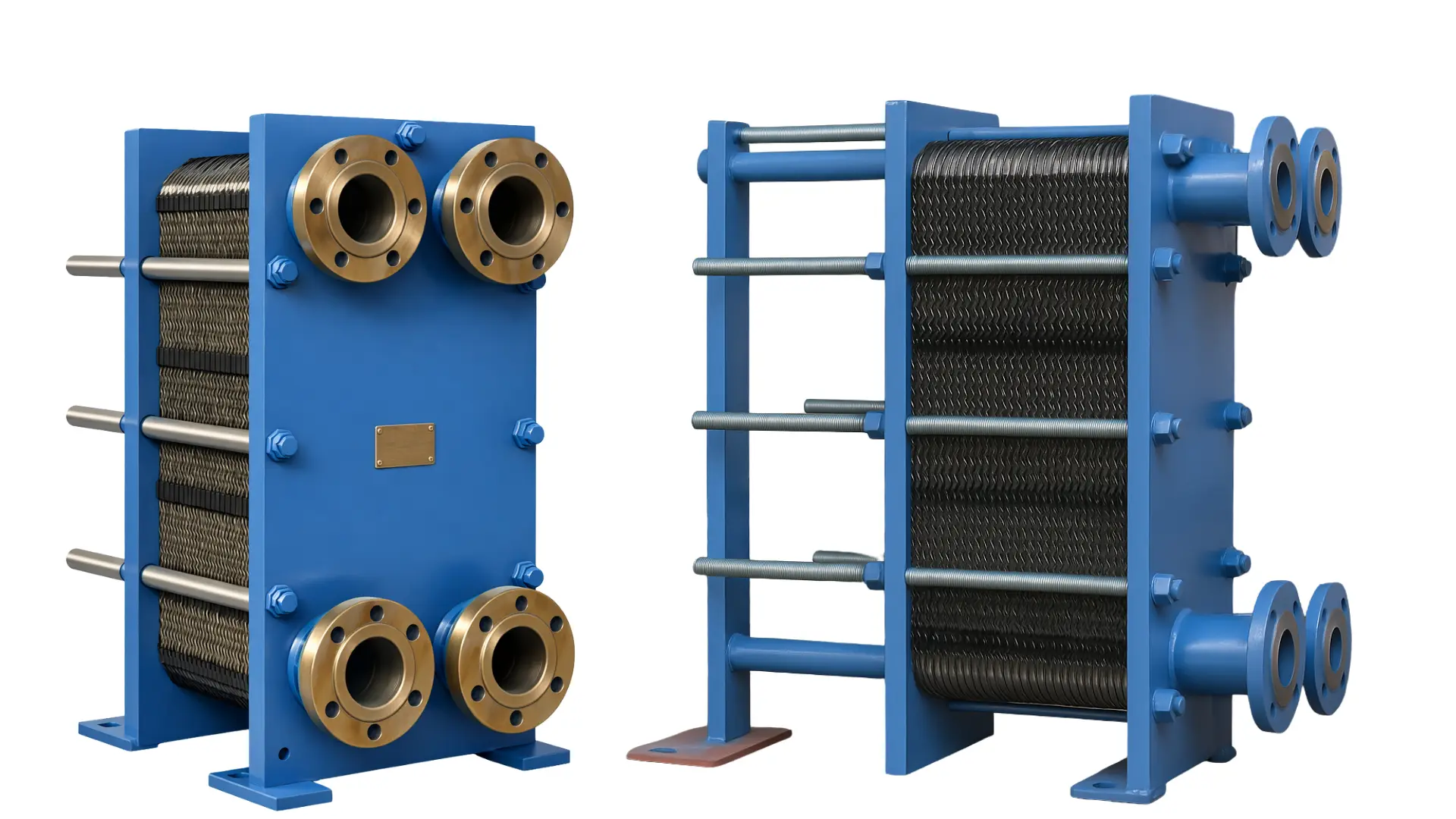
A plate heat exchanger is a device that uses thin metal plates to transfer thermal energy between two fluids without mixing them.
How It Works
- Alternating Channels: Hot and cold fluids flow through alternating gaps between the corrugated metal plates without ever mixing.
- High Surface Area: The fluids spread out thinly over a large surface area, which speeds up heat transfer.
- Turbulent Flow: Stamped or corrugated patterns on the plates create turbulence, which boosts thermal efficiency and helps stop mineral buildup.
- Sealing: Elastomeric gaskets or brazed/welded edges keep the fluids separate and route them into the right channels.
Main Types
- Gasketed Plate and Frame: Uses rubber gaskets and compression bolts; easy to take apart, clean, or expand by adding more plates.
- Brazed Plate: Permanently sealed using copper or nickel braze; very small and common in combination boilers for domestic hot water.
- Welded Plate: Plates are welded together for handling higher pressures and temperatures where gaskets fail.
Key Benefits
- Compact Size: Delivers the same thermal capacity as a shell-and-tube exchanger in a fraction of the space.
- High Efficiency: Provides a high heat-transfer coefficient and works well with small temperature differences.
- Easy Maintenance: Gasketed models can be unbolted and scrubbed or have plates replaced.
PHEs are used wherever liquids must be heated, cooled, pasteurized, condensed or evaporated: HVAC, food processing, chemicals, power, marine, refrigeration and district energy.
Note: Pressure limits, U-values, temperatures and service life in this article are typical ranges. They vary by manufacturer, model and application, so verify them against current datasheets before using them in an engineering design.
2. Operating Principle
Heat passes from the hot fluid to the cold fluid in three steps: convection to the plate, conduction through the plate wall, and convection into the other fluid.The physics of heat transfer
- Convection from the hot bulk fluid to the hot side of the plate.
- Conduction through the plate wall, typically 0.3 to 0.8 mm thick.
- Convection from the cold side of the plate into the cold bulk fluid.
1/U = 1/h_hot + R_f,hot + t/k_plate + R_f,cold + 1/h_cold
Here h is the convective coefficient on each side, t the plate thickness, k the plate's thermal conductivity and R_f the fouling resistance. The plate is thin and metallic, so its own resistance is small. The film coefficients dominate, and the corrugations are designed to raise them.
Why corrugations matter
Corrugations do several things that a flat plate cannot:- They force the fluid to change direction constantly, producing swirl and secondary flow.
- They break up the boundary layer repeatedly.
- They allow turbulence at a low Reynolds number, with transition beginning at roughly Re 10 to 400 compared with about 2,300 in a smooth tube.
- They increase the effective surface area compared with a flat plate.
- They create contact points between neighbouring plates, which support the pack against pressure.
Step-by-step flow path
- Each plate has four ports, one at each corner.
- A gasket (or brazed seal) around two ports lets the fluid pass through them and blocks the other two.
- Neighbouring plates are rotated 180°, so each channel is fed by one fluid and its neighbours by the other.
- The hot fluid fills the odd-numbered channels and the cold fluid fills the even-numbered ones.
- The fluids move across the plate in opposite directions (counter-current), which maximises the mean temperature difference.
- Each fluid leaves through its own outlet port.
The basic design equation
Q = U × A × ΔT_lm- Q: heat duty (kW)
- U: overall heat transfer coefficient (W/m²K)
- A: heat transfer area (m²)
- ΔT_lm: log mean temperature difference (K)
3.Construction
A gasketed PHE is a plate pack held in a frame; brazed and welded units replace the frame and gaskets with permanent joints.Gasketed unit: main components
| Component | Function |
|---|---|
| Heat transfer plates | Corrugated pressed sheets that carry out the heat exchange |
| Gaskets | Seal each channel and direct the flow to alternating channels |
| Fixed frame plate (head) | Rigid end plate, usually holding the connections |
| Movable pressure plate (follower) | Compresses the plate pack as the bolts are tightened |
| Upper carrying bar | Supports the weight of the plates, which hang from it |
| Lower guide bar | Keeps the plates aligned |
| Tightening bolts | Compress the pack to a fixed dimension |
| Connection ports | Nozzles (flanged, threaded or studded) for inlet and outlet pipes |
| Support column | Supports the carrying bar on long units |
How plates are manufactured
- Pressing: a flat sheet is pressed between a pair of dies in a large hydraulic press, forming the corrugation pattern in one stroke. Thickness is typically 0.3 to 0.8 mm.
- Material choice: stainless steel, titanium, nickel alloys and others, depending on the fluids.
- Gasket groove: a groove around the plate edge and ports holding the gasket.
- Quality control: plates are checked for thickness, cracks, pressing depth and flatness. Finished units are pressure tested.
Gasket attachment methods
- Glued gaskets: fixed in the groove with adhesive, the traditional method.
- Glue-free (clip-on or snap-in) gaskets: held mechanically, so replacement is faster and there is no curing time.
- Double gaskets with leak vent: an air gap between two seals makes leakage visible externally and keeps the fluids from mixing.
Brazed construction
A brazed PHE is a stack of plates with brazing filler (usually copper, or nickel for aggressive duties) between them. The stack is heated in a vacuum furnace, and the filler flows to the contact points and edges. After cooling, the plates form one sealed, pressure-resistant block. Cover plates and connection nozzles complete the unit.Welded construction
Welded designs join the plate edges by laser or TIG welding instead of gaskets. Pairs of plates may be welded together and assembled in a frame (semi-welded), or all plates may be welded into a block or a round pack inside a shell (plate-and-shell).4.Types of Plate Heat Exchangers
The main types differ in how the plates are sealed, and that sets their pressure, temperature and cleaning limits.Gasketed (GPHE)
The most common industrial type.- Strengths: can be opened for inspection and cleaning; plates can be added or removed to change capacity; plate material can be chosen for each duty.
- Limits: set by the gaskets, typically up to about 25 to 30 bar and around 150 to 200 °C.
- Typical uses: HVAC, district heating, food and beverage, general industry, marine, power.
Brazed (BPHE)
- Strengths: very compact, light and low in cost; no gaskets; often rated to 30 bar or more; excellent as a refrigerant evaporator or condenser.
- Limits: cannot be opened, and cleaning is chemical only. Suits clean fluids.
- Typical uses: heat pumps, refrigeration, domestic hot water, small HVAC systems, oil cooling.
Fusion-bonded (copper-free)
Stainless steel plates are bonded without copper filler. This suits ammonia and fluids that attack copper.Welded
- Strengths: no gaskets, so it handles aggressive chemicals, high temperature and high pressure.
- Limits: cannot be opened for mechanical cleaning; only chemical or hydraulic cleaning is possible.
- Typical uses: chemical processing, oil and gas, ammonia refrigeration.
Semi-welded (twin-plate)
Plates are welded in pairs. The welded channel carries the aggressive fluid (ammonia, refrigerant or solvent) and the gasketed channel carries the other fluid, usually water. The gasket never meets the aggressive medium, and the unit can still be opened on the gasketed side.Wide-gap and free-flow
Larger gaps, or no contact points, let fibres, crystals, slurries and particles pass without clogging. Used in sugar mills, pulp and paper, ethanol plants, wastewater and food streams with pieces.Double-wall
Each separating wall consists of two plates. If one plate leaks, the fluid escapes into the gap and out of the unit, so the two fluids never mix. Used for drinking water, pharmaceutical and food duties.Plate-and-shell
A round plate pack is welded and fitted inside a pressure shell. It handles higher pressure and temperature than gasketed units and has a smaller footprint than shell-and-tube. Used in oil and gas, power and chemical plants.Related plate-type designs
- Plate-fin heat exchanger: layers of plates and fins, usually brazed aluminium, for gases, cryogenics and aerospace.
- Printed circuit heat exchanger (PCHE): chemically etched plates diffusion-bonded together, for extreme pressure and temperature.
- Spiral heat exchanger: a pair of long plates wound into a spiral, good for viscous or fouling fluids.
5.Plate Design and Corrugation
The chevron angle sets the trade-off between heat transfer and pressure drop, and designers mix plate types in one pack to balance the two.Chevron (herringbone) pattern
The most common pattern forms a V-shape. The chevron angle (θ), measured from the flow direction, has a major effect.| Plate Type | Chevron Angle | Heat Transfer | Pressure Drop |
|---|---|---|---|
| High-theta ("hard") | Large (steep) | High | High |
| Low-theta ("soft") | Small (shallow) | Lower | Lower |
| Mixed pack | Both | Balanced | Balanced |
Other design features
- Distribution area: a zone near the ports shaped to spread flow evenly across the plate width and avoid dead spots.
- Contact points: places where neighbouring plates touch. They set the channel gap, support the plates against pressure and add turbulence.
- Port size: large ports reduce port pressure loss and flow maldistribution on big units.
- Plate size range: from small plates with 25 mm connections and about 0.03 m² area to large plates with ports over 500 mm and more than 4 m² area.
Channel gap
The average channel gap is typically 2 to 5 mm on standard plates. Wide-gap plates may have gaps of 16 mm or more.6. Materials
Plate and gasket materials must be matched to both fluids, the temperature and the cleaning chemicals, because the plates are thin and failures are rapid.Plate materials
| Material | Strengths | Typical Uses |
|---|---|---|
| Stainless steel 304 | Economical, good general corrosion resistance | Fresh water, HVAC, food |
| Stainless steel 316/316L | Better resistance to mild chlorides and chemicals | Chemicals, dairy, pharma |
| Titanium | Excellent resistance to seawater and chlorides | Marine, pools, coastal power |
| 254 SMO | High molybdenum, higher chloride resistance | Aggressive brackish and process waters |
| Nickel / Incoloy / Hastelloy | Strong acids and alkalis, high temperature | Chemical and process industries |
| Copper (brazing) | Good wetting and strength in brazed joints | HVAC and refrigeration |
| Graphite | Resists hot, strong acids | Specialty chemical duties |
Gasket materials
| Material | Typical Temperature Range* | Best For | Avoid With |
|---|---|---|---|
| NBR (nitrile) | To about 110–135 °C | Oils, fuels, water | Strong oxidizers, ozone |
| EPDM | To about 140–160 °C | Hot water, steam, many acids and alkalis | Mineral oils, fats |
| Viton (FKM) | To about 180 °C | Aggressive chemicals, hot oils | Steam, some amines |
| HNBR | Higher than NBR | Hot oils | Strong acids |
| Butyl | Up to about 150 °C | Certain acids, gases | Oils |
| Silicone | Wide range | Some food uses | Steam, high mechanical stress |
| PTFE-based | Very wide | Very aggressive media | Cold-flow issues without support |
Why material selection matters
Chlorides attack stainless steel (pitting and crevice corrosion), oils swell EPDM, and steam degrades NBR. A wrong choice causes rapid failure, so selection depends on the fluids, concentration, temperature, pressure and cleaning chemicals.7. Flow Arrangements
Counter-current flow is the standard, because it gives the largest mean temperature difference.- Counter-current: fluids move in opposite directions. Standard choice.
- Co-current (parallel): same direction, lower efficiency. Rarely used except where wall temperature must be limited.
- Single-pass: each fluid makes one pass through the pack. All connections sit on the fixed frame plate, which simplifies piping.
- Multi-pass: one or both fluids turn and make two or more passes. Used when flow rates differ widely or a long thermal length is needed. Some connections are then on the movable plate.
- Series sections: several sections for different tasks (heating, cooling, heat recovery) in one frame, with intermediate connecting plates.
- Parallel plate groups: used to reduce pressure drop at large flows.
- Temperature cross: a PHE can run with the cold outlet hotter than the hot outlet, because of true counter-current flow. This is rarely possible in a single shell-and-tube unit.
Thermal and Hydraulic Design
Sizing a PHE means finding the area that delivers the required duty at the available temperature difference, then checking that the pressure drop is acceptable.Heat duty
Q = ṁ × c_p × ΔTHeat lost by the hot fluid equals heat gained by the cold fluid, neglecting losses.
Log mean temperature difference (LMTD)
ΔT_lm = (ΔT₁ − ΔT₂) / ln(ΔT₁ / ΔT₂)For counter-current flow:
ΔT₁ = T_hot,in − T_cold,out
ΔT₂ = T_hot,out − T_cold,in.
For multi-pass arrangements a correction factor F is applied.
Overall heat transfer coefficient (U)
Approximate values for clean units:| Duty | U (W/m²K) |
|---|---|
| Water to water | 3,000 – 7,500 |
| Oil to water | 300 – 800 |
| Steam to water | 3,000 – 6,000 |
| Glycol solution to water | 2,000 – 4,500 |
| Refrigerant evaporation or condensation | 2,000 – 5,000 |
Heat transfer correlations
Plate heat transfer is usually described by a Nusselt number correlation:Nu = C × Re^n × Pr^(1/3) × (μ/μw)^0.14
C and n depend on the plate pattern; n usually lies between about 0.6 and 0.8. Manufacturers measure the constants for each plate type.
Pressure drop
Total pressure drop on one side is the sum of channel (friction) loss, port and manifold loss, and elevation head where relevant. Typical allowable values are 20 to 100 kPa per side, but they vary widely with the duty and the pumps available.Effectiveness and NTU method
When outlet temperatures are unknown, the ε-NTU method is used: NTU = UA / C_min and effectiveness ε = Q / Q_max. A PHE has a high NTU per plate, giving effectiveness of 90 to 95% or higher in counter-current flow.Thermal length
Thermal length describes how much temperature change a plate achieves relative to the driving force. High-theta plates have a high thermal length and suit duties where the temperature change is large compared with the approach.Flow maldistribution
Uneven flow across the plate width or between channels reduces performance. Good port and distribution-area design, suitable port velocities and avoiding extremely long plate packs keep it small.Two-phase duties: condensation and evaporation
Brazed PHEs are widely used as refrigerant evaporators and condensers. Key points:- Very high heat transfer coefficients with phase change
- Small refrigerant charge compared with other designs
- Need for correct distribution of two-phase flow
- Careful design for vapour velocity and pressure drop
Fouling, Scaling and Corrosion
Fouling lowers capacity and raises pumping cost, and corrosion in a thin plate can quickly become a through-wall leak.Types of fouling
| Type | Cause | Example |
|---|---|---|
| Particulate | Suspended solids settle | Sand, silt, rust |
| Crystallization (scaling) | Salts precipitate at hot surfaces | Calcium carbonate in hard water |
| Biological | Growth of microorganisms | Slime in cooling water |
| Corrosion fouling | Corrosion products deposit | Iron oxide |
| Chemical reaction | Fluid reacts or polymerizes at the wall | Polymerization in hydrocarbons |
Effects
- Lower heat transfer and reduced capacity
- Higher pressure drop and pumping energy
- Local hot spots and further corrosion under deposits
How PHEs resist fouling
High turbulence and high wall shear stress keep surfaces cleaner. In many duties the fouling factors are only a fraction of those used for tubular units.Reducing fouling
- Install strainers (often 0.5 to 2 mm mesh) upstream
- Use suitable water treatment (softening, inhibitors, filtration)
- Keep velocities within the recommended range
- Avoid stagnant zones and long idle periods with dirty fluid
- Choose wide-gap plates for particle-laden or fibrous streams
Corrosion types in PHEs
- Pitting corrosion: small local holes, typical with chlorides on stainless steel
- Crevice corrosion: under gaskets and contact points
- Stress corrosion cracking: from tensile stress, chlorides and heat
- Galvanic corrosion: between dissimilar metals
- Erosion-corrosion: from high-velocity fluid with particles
Cleaning and Maintenance
Monitoring pressure drop and temperatures is the best way to know when a PHE needs cleaning.Cleaning methods
Clean-in-place (CIP). Cleaning solution is circulated through the exchanger without opening it, normally against the usual flow direction and at higher velocity. It is standard in dairy and food plants.Manual cleaning (gasketed units).
- Isolate the unit, drain it and let it cool.
- Loosen and remove the tightening bolts evenly.
- Slide the plates apart and inspect them.
- Clean with a soft brush and water or a suitable cleaner. Never use steel wire brushes.
- Inspect gaskets and replace damaged ones.
- Reassemble in the correct order and tighten to the specified dimension.
Chemical cleaning
- Acids (citric, nitric, phosphoric, sulfamic) remove scale and metal oxides.
- Alkaline cleaners remove oil, grease and organic deposits.
- Avoid hydrochloric acid and chloride-containing cleaners on stainless steel.
- Follow the manufacturer's limits on concentration, temperature and time.
Brazed units: Chemical cleaning only (CIP loops), since they cannot be opened.
Routine maintenance
- Record inlet and outlet temperatures and pressure drops regularly, and watch the trends.
- Inspect gaskets for hardening, cracks and permanent compression set.
- Do not tighten beyond the nameplate dimension.
- Pressure test after reassembly.
- Replace damaged or corroded plates.
- Keep spare gaskets and a few spare plates.
- Keep records of cleaning and maintenance dates.
Service life
- Plates: commonly 15 to 20 years or more with suitable materials and water quality
- Gaskets: commonly 5 to 10 years, shorter at high temperature or with aggressive fluids
Applications
PHEs serve any clean liquid-to-liquid heating, cooling or heat-recovery duty at moderate pressure and temperature.| Industry | Typical uses |
|---|---|
| HVAC and building services | Isolating chiller water from building circuits; free-cooling with cooling towers or natural water; boiler, solar or heat-pump heating; domestic hot water |
| District heating and cooling | Substations that separate the network from the building system; heat transfer stations using heavy-duty gasketed or welded units |
| Food and beverage | Pasteurizing and cooling milk, juice, beer, wine, sauces, soups and edible oils; CIP and 3-A or similar hygienic compliance |
| Pharmaceutical and biotech | Process heating and cooling; water-for-injection and purified-water loops; double-wall plates where contamination must be prevented |
| Chemical and petrochemical | Process heating, cooling and heat recovery; corrosive media using titanium, nickel alloys or welded designs |
| Power generation | Closed-circuit cooling; lube-oil and generator coolers; feedwater heating and condensate cooling |
| Marine and offshore | Jacket-water, lube-oil and central cooling with titanium plates for seawater; fresh-water generators; platform heating and cooling |
| Refrigeration and heat pumps | Evaporators, condensers, sub-coolers, economizers and desuperheaters, mostly brazed or semi-welded |
| Oil and gas | Crude preheating; glycol and amine services; welded or plate-and-shell units |
| Data centres | Liquid-cooling loops and free-cooling; heat recovery from servers for district heating |
| Pulp and paper, sugar, ethanol | Wide-gap units for fibre-laden and crystal-laden liquids |
| Industrial heat recovery | Recovering heat from process water, wastewater and hot effluent to preheat feed or building water |
| Swimming pools and spas | Heating pool water in chlorine-resistant titanium units |
| Renewable energy | Solar thermal glycol-to-water loops; geothermal isolation of mineral-rich ground water from the building loop |
| Steel and metals | Quench-water and process-cooling circuits |
Milk pasteurization example
High-temperature short-time (HTST) pasteurization holds milk at about 72 °C for 15 seconds, then cools it. The regeneration section recovers heat from the hot product to preheat the incoming product, often recovering 90% or more of the heat.Advantages and Limitations
A PHE is efficient, compact and serviceable, but its pressure, temperature and fluid-cleanliness limits are tighter than those of a shell-and-tube unit.Advantages
- High thermal efficiency from high heat transfer coefficients
- Compact size, saving space and weight
- Lower cost per unit of heat transfer area
- Close temperature approach, down to 1 to 2 °C
- Temperature cross possible
- Easy access for cleaning and inspection (gasketed type)
- Flexible capacity by adding or removing plates
- Low liquid hold-up, giving fast response and small fluid volume
- Lower fouling tendency thanks to turbulence
Limitations
- Lower pressure and temperature limits for gasketed units
- Gaskets limit chemical compatibility and need replacement
- Narrow channels can block with fibres or large particles unless wide-gap plates are used
- Not ideal for very high-pressure gases or large vapour volumes
- Brazed units cannot be opened or repaired
- Pressure drop can be high if the unit is poorly selected
- Leak risk from gaskets if assembled or tightened wrongly
Comparison with Other Heat Exchangers
Use a PHE for clean liquid-to-liquid duties at moderate pressure and temperature; use shell-and-tube for very high pressure or temperature, or very dirty services.| Feature | Gasketed PHE | Brazed PHE | Welded PHE | Shell-and-tube | Spiral | Plate-fin |
|---|---|---|---|---|---|---|
| Thermal efficiency | Very high | Very high | Very high | Moderate | Good | High (gases) |
| Compactness | High | Very high | High | Low | Medium | Very high |
| Pressure limit | Medium | Medium–high | High | Very high | Medium | Medium–high |
| Temperature limit | Medium | Medium–high | High | Very high | High | Medium |
| Mechanical cleaning | Yes | No | Limited | Yes (tube side) | Yes | Difficult |
| Fouling fluids | Fair | Poor | Fair | Good | Very good | Poor |
| Expandable | Yes | No | Limited | Limited | No | No |
| Typical cost | Low | Lowest | Higher | Higher | Higher | High |
| Typical fluids | Liquids | Clean liquids, refrigerants | Aggressive fluids | Almost any | Slurries, viscous | Gases |
Selection and Sizing
Selection starts from the fluids, duty and allowable pressure drop; manufacturers' software then finds a plate pattern and count that meet them.Information required
- Hot and cold fluid names and compositions
- Flow rates or the required heat duty
- Inlet and outlet temperatures
- Physical properties (density, viscosity, specific heat, thermal conductivity)
- Allowable pressure drop on each side
- Design and operating pressure and temperature
- Fouling tendency
- Material requirements for plates and gaskets
- Space, orientation and connection requirements
- Applicable standards and certificates
Selection steps
- Calculate the heat duty and check the heat balance.
- Calculate the LMTD.
- Estimate U.
- Find the required area and add margin (commonly 10 to 25%).
- Choose the plate pattern, size and number of plates.
- Check pressure drop and velocity on each side.
- Check mechanical design (pressure, temperature, frame, nozzles).
- Confirm materials and gaskets.
- Compare options on cost, efficiency, footprint and maintenance.
Cost factors
Plate material, number and size of plates, frame rating, gasket material, certification requirements, brand and customization. Brazed units are generally the least expensive; large titanium, welded or high-pressure units cost more.Installation and Operation
Most PHE damage comes from pressure surges, thermal shock and over-tightening, so installation and start-up follow a set routine.Installation
- Place on a level, rigid base with enough side clearance to open the pack (at least the pack length plus working space).
- Install isolation valves, strainers, vents and drains, and fit pressure and temperature gauges at the inlets and outlets.
- Support the piping separately so the connections are not stressed.
- Leave room for lifting equipment for large plates.
- Insulate if heat loss or personnel protection is required.
Commissioning
- Check bolt tightness against the nameplate dimension.
- Fill the unit slowly and vent all air.
- Start the pumps with the discharge valve partly closed and open gradually.
- Raise temperature gradually.
- Check for leaks at gaskets and connections.
- Record initial pressure drops and temperatures as a baseline.
Operating cautions
- Do not exceed the rated pressure or temperature.
- Avoid pressure surges and water hammer.
- Avoid rapid temperature changes (thermal shock).
- Keep the pressure difference between the two sides within the permitted value.
- Do not run with only one side filled.
- Shut down in the order the manufacturer advises.
Troubleshooting
Most faults trace back to fouling, gaskets or trapped air.| Symptom | Likely cause | Remedy |
|---|---|---|
| Lower heat transfer | Fouling, scaling, trapped air, low flow | Clean, vent, verify flow |
| High pressure drop | Blocked channels or strainer, excess flow | Clean, check strainer and flow |
| External leak | Worn, misplaced or hard gasket; loose pack | Replace the gasket, re-align, retighten |
| Fluid mixing (internal leak) | Cracked or corroded plate | Locate by pressure test, replace plate |
| Noise or vibration | Cavitation, two-phase flow, water hammer | Adjust pressure and flow, vent air |
| Premature gasket failure | Wrong material, overheating, chemicals | Select proper elastomer, review conditions |
| Outlet temperature drifts | Fouling or a changed duty | Clean, review the design |
| Frost or freezing | Low temperature on one side | Maintain flow, add glycol, use controls |
Leak testing: Isolate one side, pressurize it, and check the other side for a pressure rise or liquid. Dye-penetrant testing can locate cracked plates.
Standards and Regulations
The applicable codes depend on region, industry and fluid.- ASME Boiler and Pressure Vessel Code, Section VIII: pressure vessel design in the United States
- PED (Pressure Equipment Directive 2014/68/EU): European pressure equipment requirements
- EN 13445 and AD 2000: European design codes
- API 662: plate heat exchangers for the petroleum and natural gas industries
- 3-A Sanitary Standards: dairy and food equipment in the United States
- NSF/ANSI and local drinking-water approvals: equipment in contact with potable water
- ISO 9001 and ISO 14001: quality and environmental management
- Marine classification societies (DNV, Lloyd's Register, ABS): shipboard use
- Local regulations on refrigerants, pressure equipment and hygiene
Energy Efficiency and Sustainability
PHEs save energy mainly by recovering low-grade heat that other exchangers cannot use.- Waste-heat recovery: a close temperature approach lets PHEs reuse low-grade heat, cutting fuel and electricity use.
- Heat pumps and district energy: PHEs are essential components and connect low-temperature sources to heating networks.
- Lower material use: compact designs use less metal, space and support structure.
- Reduced refrigerant charge: brazed units hold far less refrigerant than larger exchangers.
- Recyclability: stainless steel and titanium plates can be recycled at end of life.
- Operational efficiency: regular cleaning keeps pressure drop and pumping energy low.
- Life-cycle thinking: a higher-grade material or larger unit may cost more at first but lower energy use and maintenance over its life.


