

28-04-2026
How Does a Heat Exchangers Work?
What is a Heat exchanger
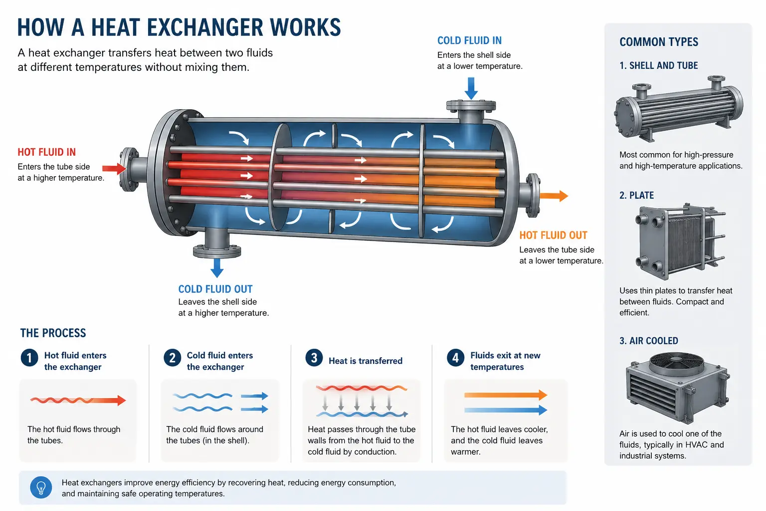
A heat exchanger is a device engineered to transfer thermal energy (heat) between two or more fluids (liquids, gases, or a combination of both) without allowing them to mix.Its core purpose is to regulate temperatures, recover waste heat, and ensure safe, efficient operations across countless industrial, commercial, and residential applications.
Key Characteristics & Working Principle
- The Driving Force: Heat naturally flows from a high-temperature fluid to a low-temperature fluid via a thermal gradient.
- Fluid Separation: In most designs (indirect contact), a solid dividing wall—typically made of a highly conductive metal like copper, aluminum, or stainless steel—keeps the fluids physically separate to prevent contamination.
- Thermodynamic Process: Thermal energy moves through the system via convection (from the hot fluid to the wall), conduction (through the metal wall), and convection (from the wall to the cold fluid).
Common Everyday and Industrial Examples
- Automotive Radiators: Engine coolant absorbs heat from the car engine and passes through radiator tubes, where outside air blows across them to dissipate the heat.
- HVAC and Refrigeration: Air conditioners and heat pumps use evaporator and condenser coils to transfer heat between refrigerant loops and indoor/outdoor air.
- Power Plants & Refineries: Large shell-and-tube heat exchangers condense exhaust steam back into water or manage aggressive chemical reactions under high pressures.
How do heat exchangers work?
Heat exchangers operate on fundamental principles of thermodynamics and heat transfer, specifically utilizing conduction and convection to move thermal energy from one fluid to another without mixing them.The Step-by-Step Working Mechanism
- Temperature Difference (The Driving Force): For heat transfer to occur, there must be a temperature difference between the two fluids. Heat naturally flows from the higher-temperature fluid to the lower-temperature fluid, driven by this thermal gradient.
- Convection (Fluid to Wall): The hot fluid flows along one side of a solid barrier (usually a metal wall or tube). Heat moves from the core of the hot fluid to the surface of the barrier through fluid motion and turbulence, a process known as forced convection.
- Conduction (Through the Barrier): Once the thermal energy reaches the solid barrier, it is transferred entirely through the material via conduction. Metals like copper, aluminum, and stainless steel are typically used because they have high thermal conductivity, allowing heat to pass through quickly and efficiently with minimal resistance.
- Convection (Wall to Fluid): On the other side of the barrier, the cooler fluid flows past the wall. The heat conducted through the metal is transferred to this cooler fluid via convection, raising its temperature while the original fluid cools down.
Flow Arrangements
The efficiency of a heat exchanger depends heavily on how the two fluids flow relative to one another:Counter-Flow (Countercurrent):
- How it works: The two fluids enter from opposite ends and flow in parallel directions opposite to each other.
- Why it’s efficient: It maintains a consistent temperature difference across the entire length of the exchanger, allowing it to recover the highest amount of heat (often achieving over 90% thermal efficiency).
Parallel-Flow (Co-current):
- How it works: Both fluids enter the exchanger from the same end and travel in the same direction.
- Why it’s used: Temperatures quickly equalize between the two fluids, making it less efficient than counter-flow, but useful when a material needs to be brought to a specific intermediate temperature gradually.
Cross-Flow:
- How it works: The two fluids flow at right angles to each other (perpendicular).
- Why it’s used: Common in applications like car radiators or air-conditioning coils, where ambient air is forced across a perpendicular array of liquid-carrying tubes.
Different types of heat exchanger
Heat exchangers are categorized in a few different ways depending on their construction design, how the fluids flow, and the nature of heat transfer.1. Classification by Construction (Physical Design)
Shell and Tube Heat Exchangers
- Design: Consists of a large cylindrical pressure vessel (the shell) packed with a bundle of pipes (tubes). One fluid runs through the tubes, while the other flows around them inside the shell. Baffles are often used to direct fluid flow and maximize turbulence.
- Best for: High-pressure and high-temperature industrial processes, power plants, and oil refineries.
Plate Heat Exchangers
- Design: Built using a series of thin, corrugated metal plates clamped together. Fluids travel through alternating channels between the plates.
- Best for: Applications requiring a massive surface area in a compact footprint, such as HVAC systems, refrigeration, and dairy/food processing.
Double Pipe (Tube-in-Tube) Heat Exchangers
- Design: A simple concentric design where a smaller pipe is nested inside a larger outer pipe. One fluid flows through the inner pipe and the other flows through the annular space between them. Best for: Small-scale applications, low flow rates, and situations requiring easy maintenance and cleaning.
Finned-Tube (Air-Cooled) Heat Exchangers
- Design: Tubes that carry hot liquid are fitted with external "fins" (thin metal sheets) to drastically increase the surface area exposed to the air. Fans are typically used to blow ambient air across them.
- Best for: Locations where water is scarce, car radiators, and air-conditioning condenser units.
2. Classification by Heat Transfer Process
Recuperative (Surface) Heat Exchangers:
The most common type, where hot and cold fluids flow simultaneously through separate channels/paths and exchange heat through a solid separating wall without ever mixing.Regenerative Heat Exchangers:
Uses a single thermal storage medium (a "matrix" or wheel). The hot fluid passes through it first, heating up the matrix. The fluid is then cut off, and the cold fluid passes through the same matrix, absorbing the stored heat.Direct Contact (Recuperative) Heat Exchangers:
The hot and cold fluids physically mix with one another to transfer heat (e.g., cooling towers, where warm water is sprayed directly into a stream of air).3. Classification by Flow Arrangement
- Counter-Flow: Fluids enter from opposite ends and flow in reverse directions relative to each other. This is the most efficient configuration because it maintains the highest temperature gradient across the length of the exchanger.
- Parallel (Co-Flow): Fluids enter from the same end and travel in the same direction. Temperatures quickly equalize, making it less thermally efficient.
- Cross-Flow: Fluids flow perpendicular (at right angles) to each other, commonly seen in automotive radiators and cross-ventilation systems.
Common heat exchanger applications
Heat exchangers play a critical role across residential, automotive, and heavy industrial sectors. Their primary functions are to regulate temperatures, ensure safety, and maximize energy efficiency by reusing waste heat.1. HVAC and Refrigeration (Buildings & Homes)
- Air Conditioning & Heat Pumps: Evaporator and condenser coils act as heat exchangers, absorbing heat from indoor air to cool a building, or reversing the cycle to provide heating.
- Space Heating: Boilers use heat exchangers to transfer thermal energy from hot water or steam into the air or secondary water loops that circulate through radiators.
2. Automotive and Transportation
- Car Radiators: Finned-tube heat exchangers cool hot engine coolant by passing ambient air across the tubes, preventing the engine from overheating.
- Oil Coolers: Regulate the temperature of engine oil or transmission fluid to maintain proper viscosity and protect moving parts.
- Intercoolers: Used in turbocharged engines to cool compressed air before it enters the cylinders, boosting engine efficiency and power.
3. Power Generation
- Condensers and Steam Generators: In nuclear, coal, or gas-fired power plants, massive shell-and-tube heat exchangers condense exhaust steam back into liquid water so it can be re-pressurized and reused in a continuous closed loop.
- Nuclear Applications: Specialized heat exchangers safely transfer heat from radioactive primary coolant loops to secondary loops without letting radioactive materials mix with the environment or turbine systems.
4. Chemical and Petrochemical Processing
- Reaction Temperature Control: Chemical reactions often require precise heating or cooling to proceed safely and yield the correct product. Heat exchangers maintain these exact thermal boundaries.
- Waste Heat Recovery: Chemical plants capture high-temperature exhaust gases or waste liquids and route them through heat exchangers to pre-feed incoming materials, drastically lowering fuel consumption and saving operational costs.
5. Food, Beverage, and Pharmaceuticals
- Pasteurization: Plate heat exchangers are heavily used in the dairy and beverage industries to rapidly heat milk or juices to safe temperatures and immediately cool them back down, preserving flavor and extending shelf life.
- Sanitary Processing: Built from corrosion-resistant materials (like high-grade stainless steel), these units ensure zero contamination during the processing of medicines, cosmetics, and ingestible goods.
6. Electronics and Data Centers
- Data Center Cooling: High-density server farms rely on liquid-to-air or liquid-to-liquid heat exchangers to dissipate massive amounts of heat, preventing hardware meltdowns and maintaining uptime.
- Heat Sinks: Passive heat exchangers attached to computer processors (CPUs and GPUs) draw heat away from microchips and transfer it into the surrounding air or fluid.
Design & manufacturing heat exchangers
Designing and manufacturing heat exchangers is a complex engineering discipline that combines thermodynamics, fluid mechanics, material science, and precision fabrication. The process ensures that the unit can handle specific thermal loads, operating pressures, and corrosive environments safely and efficiently.Phase 1: The Design Process
Engineers follow a two-step design approach—first calculating the thermal requirements, and then ensuring the mechanical structure can withstand operating conditions.1. Thermal Design (Sizing and Rating)
- Determining Heat Duty: Calculating the total amount of heat that needs to be transferred per unit of time (measured in Watts or BTU/hr).
- Fluid Properties: Factoring in density, specific heat, viscosity, and thermal conductivity of both the hot and cold fluids at operating temperatures.
- Calculating Surface Area ($A$): Using core thermodynamic formulas—such as the Log Mean Temperature Difference (LMTD) method or the Effectiveness-NTU method—to determine the required heat transfer surface area.
- Pressure Drop Constraints: Balancing high turbulence (which improves heat transfer) with allowable pressure drop limits so pumps and compressors don't overload.
2. Mechanical Design
- Material Selection: Choosing metals (like carbon steel, stainless steel, titanium, copper, or Inconel) based on fluid corrosiveness, temperature limits, and mechanical strength.
- Code Compliance: Designing to recognized industry standards and safety codes (such as ASME Section VIII for pressure vessels or TEMA standards for shell-and-tube exchangers).
- Wall Thickness and Stress Analysis: Calculating required thicknesses to withstand internal and external operating pressures, thermal expansion stresses, and vibrations.
Phase 2: The Manufacturing Process
Once the blueprints and engineering drawings are finalized, fabrication requires high-precision metalworking and stringent quality control.1. Component Fabrication
- Tube and Plate Formation: Tubes are extruded or drawn to length, while metal plates for plate heat exchangers are stamped using heavy hydraulic presses to create specific corrugated patterns.
- Shell and Header Rolling: Large metal sheets are rolled and welded to form cylindrical shells, headers, and pressure containers.
- Baffle and Tubeshheet Drilling: CNC machines drill precise hole patterns into thick metal plates (tubesheets) where tubes will be inserted.
2. Assembly and Joining
- Tube Insertion and Expansion: Tubes are slid through baffles and into the tubesheet holes. They are then permanently locked and sealed using mechanical roller expansion or hydraulic expansion to create a leak-proof metal-to-metal seal.
- Welding: High-precision welding (such as TIG, MIG, or automated orbital welding) is used to join tubes to tubesheets, attach nozzles, and seal structural seams.
- Brazing and Soldering: For compact units like plate-fin or brazed plate heat exchangers, components are assembled with brazing filler metal and placed in a vacuum or controlled-atmosphere furnace to melt and bond the joints simultaneously.
3. Quality Control and Testing
- Non-Destructive Testing (NDT): Welds and materials are inspected using X-ray (radiography), ultrasonic testing, or dye penetrant inspection to detect internal flaws or micro-cracks.
- Hydrostatic Testing: The assembled heat exchanger is pressurized with water (typically at 1.5 times its design pressure) to verify structural integrity and check for any leaks before shipment.
Common materials used in heat exchangers
Choosing the right material for a heat exchanger is critical. The material must possess high thermal conductivity for efficient heat transfer while withstanding high operating temperatures, pressures, and corrosive fluids.1. Metals and Alloys (Most Common)
Stainless Steel (e.g., 304, 316, 316L)
- Properties: Excellent corrosion resistance, good strength, and durability. Grade 316 contains molybdenum, making it highly resistant to chlorides and chemical attacks.
- Applications: Food and beverage processing, pharmaceuticals, chemical plants, and marine environments.
Copper and Copper Alloys (e.g., Brass, Cupro-Nickel)
- Properties: Exceptionally high thermal conductivity and naturally antimicrobial. Cupro-nickel is especially resistant to saltwater corrosion.
- Applications: HVAC coils, domestic water heaters, car radiators, and marine/offshore heat exchangers.
Carbon Steel
- Properties: High mechanical strength, easy to fabricate, and cost-effective, though prone to rusting if untreated.
- Applications: Power generation, oil refineries, and closed-loop industrial systems where fluids are non-corrosive.
Aluminum
- Properties: Lightweight, highly thermally conductive, and forms a protective oxide layer that resists corrosion.
- Applications: Automotive radiators, intercoolers, aerospace systems, and air-cooled heat exchangers.
Titanium
- Properties: Ultimate corrosion resistance—especially against aggressive chemicals like seawater, chlorine, and acids—with high strength-to-weight ratio.
- Applications: Desalination plants, chemical processing, and coastal power stations.
Installations and aftermarket & service support
Ensuring long-term reliability, maximum thermal efficiency, and minimal operational downtime requires careful attention to installation, aftermarket care, and service support.1. Installation Best Practices
A successful installation prevents premature structural failure, stress fractures, and efficiency loss.- Foundation and Alignment: The heat exchanger must be mounted on a flat, rigid, non-vibrating base. Pipe connections must align precisely with the nozzles to avoid placing mechanical stress or bending moments on the equipment.
- Thermal Expansion Provision: Because fluids cause significant temperature swings, equipment expands and contracts. Systems must incorporate expansion joints, flexible connectors, or floating heads to absorb thermal growth.
- Access and Clearance: Adequate physical clearance must be left around the unit (especially in front of shell-and-tube exchangers) to allow for pulling tube bundles or opening plate packs during future maintenance.
- Instrumentation Setup: Installing pressure gauges, temperature sensors, and flow meters on both inlet and outlet lines allows operators to monitor the pressure drop and thermal baseline from day one.
2. Aftermarket Support & Maintenance
Heat exchangers do not typically fail suddenly; they degrade silently through fouling, scaling, or corrosion. A robust aftermarket program focuses on three core pillars:A. Performance Monitoring
Tracking the overall heat transfer coefficient ($U$-value) and pressure drop helps detect problems early. A sudden spike in pressure drop paired with a drop in thermal performance is the classic indicator of internal fouling.B. Cleaning and Remediation
- Mechanical Cleaning: Utilizing specialized brushes, scrapers, or high-pressure hydro-blasting to clear debris, biological growth, and hard mineral scale out of tubes.
- Chemical Cleaning (CIP - Clean-in-Place): Circulating specialized chemical solutions (like mild acids or tailored descalers) to dissolve internal deposits without stripping protective metal oxide films.
- Backflushing: Reversing fluid flow temporarily in plate heat exchangers to dislodge trapped soft sediments.
C. Non-Destructive Testing (NDT) & Inspections
- Eddy Current Testing (ECT) / Remote Field Testing (RFT): Electromagnetic testing used to scan tubes for internal pitting, thinning, and wall degradation without destroying them.
- Hydrostatic Pressure Testing: Pressurizing the unit (often to 1.5 times design pressure) during turnarounds to verify structural integrity and verify zero leakage across joints or gaskets.
3. Spare Parts & Lifecycle Services
Comprehensive aftermarket support ensures critical components are readily available to prevent extended plant shutdowns:- Gasket and Seal Replacements: Plate heat exchangers rely heavily on elastomer gaskets (such as EPDM, NBR, or Viton). Over time and cyclic heat exposure, these harden or crack. Keeping OEM-certified replacement gaskets on hand prevents cross-contamination and external leaks.
- Tube Plugging vs. Retubing: If a tube breaches, maintenance teams typically use specialized metal plugs to seal off the damaged tube at both tubesheet ends as a temporary fix. Once the plugged percentage reaches a critical threshold (typically 5% to 10% of total capacity), a full bundle retubing or unit replacement is scheduled.
- Emergency Field Services: Major industrial equipment suppliers often provide field-machining, retrofitting, emergency leak-sealing, and rapid bundle-replacement turnarounds to get critical chemical plants, power stations, and refineries back online safely.


